Bolted Joints
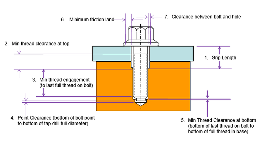
These are the seven stacks that should be done
for a bolted joint with a fixed fastener.
Depending on the situation, they might not all be necessary.
1. Grip Length is used to verify that there is sufficient bolt stretch for maintaining clamp load.
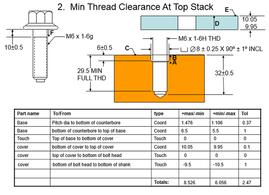
2. Min Thread Clearance at top verifies that the bolt will not run out of thread at the top before it is fully torqued down.
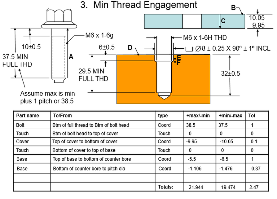
3. Min Thread Engagement verifies that the bolt engages a sufficient number of threads to hold the clamp load.
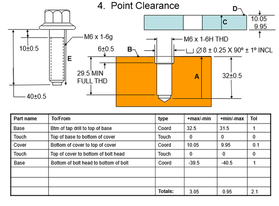
4. Point Clearance at bottom verifies that the bolt’s point (if it has one) will not bottom out against the bottom of the tap drill.
5. Min Thread Clearance at bottom verifies that the bolt thread will not bottom out in the thread in the base.
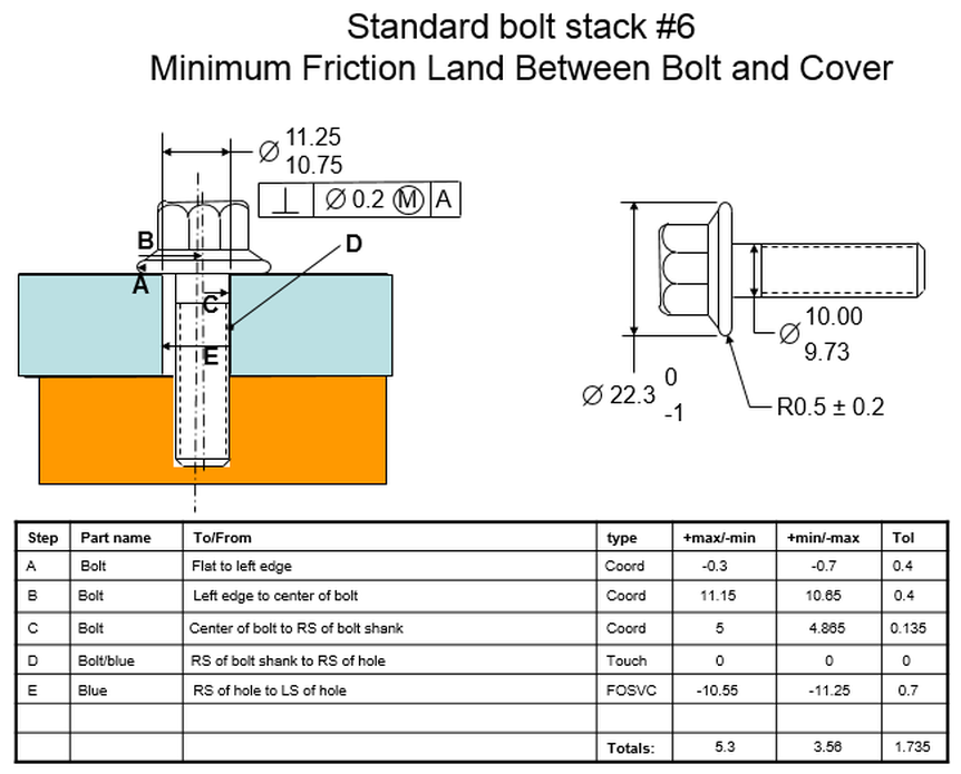
6. Minimum Friction Land verifies that the there will be support under the bolt head for a full 360 degrees. If the stack using only one bolt and hole shows a problem, it may be necessary to do a second stack. Other factors that locate the cover to the base might prevent the situation that shows a problem when looking at only the one bolt in the one hole.
7. Clearance between bolt and hole verifies that the bolt will fit through the hole.
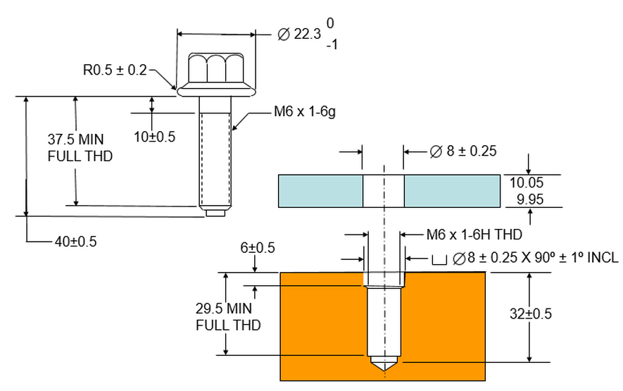
These are the dimensions for the components
used in bolt stacks
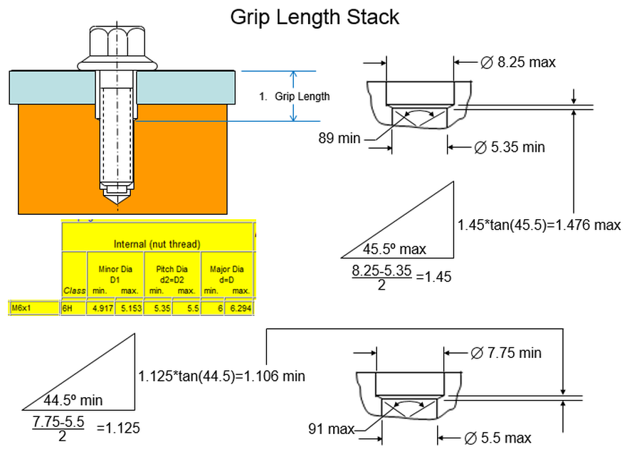
The Grip Length stack involves extra
calculations because of the counter sink.
We must determine the max and min vertical distance between the bottom
of the full diameter of the counterbore and the point at which the
countersink intersects the pitch diameter of the thread.
We create two triangles – one for the max condition and one for the min condition. For the max distance, the horizontal length of the triangle will be the max radius of the countersink minus the min radius of the pitch diameter. The angle is the max angle as shown.
For the min vertical distance, the horizontal length of the triangle is the min radius of the countersink minus the max radius of the pitch diameter. The angle is the min angle shown.
We use trigonometry to calculate the max and min vertical distance between the bottom of the countersink and the pitch diameter.
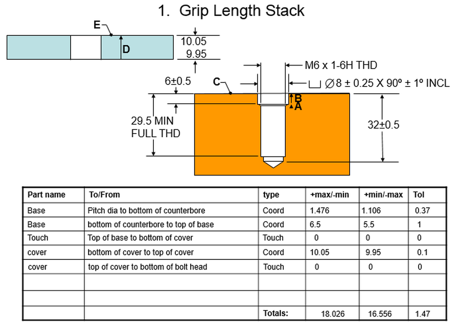
The stack path starts at the pitch
diameter. We use
the max and min distances calculated above to go from there to the
bottom of the counterbore.
We go from the bottom of the counterbore to the top of the base. Then we have a touch point going from the top of the base to the bottom of the cover.
We use the size dimension to go from the bottom of the cover to the top of the cover. We have another touch point between the top of the cover and the bottom of the bolt head.
The "Min thread clearance at top" stack repeats the Grip Length stack and then adds the extra step of going from the bottom of the bolt head to the bottom of the shank
The "Min thread clearance at top" stack repeats the Grip Length stack and then adds the extra step of going from the bottom of the bolt head to the bottom of the shank
The "Min thread engagement" stack starts at the bottom of the thread in the bolt The bolt specifies only a min full thread. We must assume a max. Commonly we will assume that the max thread is the min full thread plus one pitch. The M6 x 1-6g designation specifies a pitch of 1. So we assume a max of 38.5.
From the bottom of the thread, the stack goes to the bottom of the head of the bolt.
The bottom of the bolt head touches the top of the cover. The stack goes from the top of the cover to the bottom of the cover and touches the top of the base.
It goes from the top of the base to the bottom of the counterbore, and then from the bottom of the counterbore to the top of the pitch diameter in the base. We get the max and min values for this step from the grip length stack.
The "Point clearance" stack starts at the bottom of the full diameter of the tap drill. From there it goes to the top of the base.
It touches the bottom of the cover, goes through the cover, and touches the bottom of the bolt head.
Finally it goes from the bottom of the bolt head to the very bottom of the bolt.
The "Min thread clearance at bottom" stack starts at the bottom of the full thread in the base. Like the thread on the bolt, only a min full thread is specified. So we must assume a max. We will assume one pitch like we did on the bolt. So we assume a max of 30.5.
From the bottom of the thread in the base, we go to the top of the base.
The top of the base touches the bottom of the cover, and the stack proceeds through the cover.
The top of the cover touches the bottom of the head of the bolt and finally goes from the bottom of the head of the bolt to the bottom of the thread on the bolt. Once again we use the min full thread of 37.5 and assume a max full thread of 38.5.
The "Minimum friction land" stack analyzes the friction area between the bolt head and the cover. We need to make sure that there is no gap between the edge of the flat surface on the bolt head and the clearance hole in the cover.
Note that in the example below, the cover is pushed against one side of the bolt. This is the worst case situation. Most of the time, the cover will be located relative to the base in such a way that the side of the hole in the cover will never be pushed against the side of the bolt.
If this stack shows a problem, another stack could be done that includes the locating scheme between the cover and the base. It may be that when the cover is located relative to the base, the bolt will be more centered in the clearance hole and there will not be a gap between the flat surface on the bolt head and the clearance hole in the cover. See the final section of this book to see how to do a stack that includes locating the cover relative to the base.
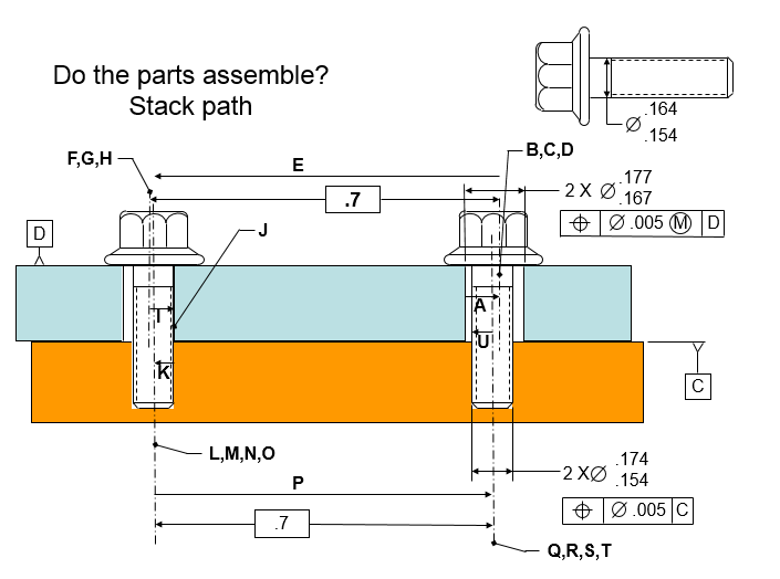
Finally we have the stack to determine whether or not bolts will fit through holes.
In order to determine whether or not the parts will assemble, we push the cover against the inside of the left bolt and calculate whether or not there is a gap between the left side of the right hole and the left side of the right bolt.
The stack path is shown below:
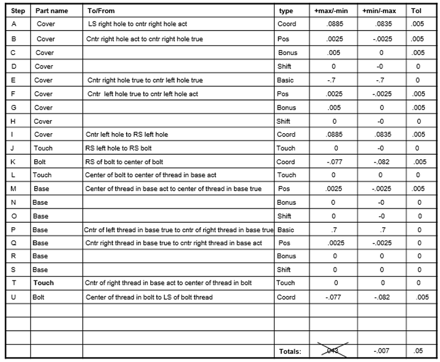
Below is the step by step solution to the stack.
Note that we are looking for a minimum gap. Therefore the max column is crossed out in the line for the totals.
Also note that the stack shows that it's possible to have a situation in which the parts do not assemble.
Below is the step by step solution to the stack.
Note that we are looking for a minimum gap. Therefore the max column is crossed out in the line for the totals.
Also note that the stack shows that it's possible to have a situation in which the parts do not assemble.

