Datum scheme for a cover
It's very common to attach a cover to something. There is a classic way to set up the datums for a typical cover. This datum scheme is functional and does a great job of constraining the six degrees of freedom.
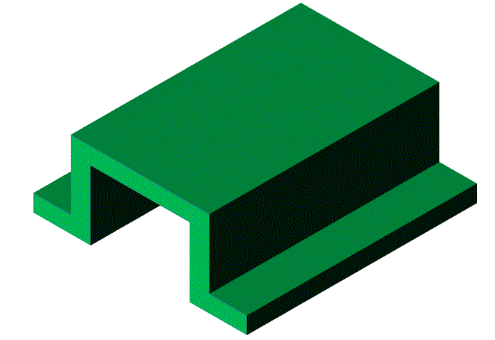
We see our cover below before any holes are drilled or punched or formed in it.
We want the bottom of the flanges to sit on a base, and we want to locate the cover to bolts or dowels in the base.
We see our cover below before any holes are drilled or punched or formed in it.
We want the bottom of the flanges to sit on a base, and we want to locate the cover to bolts or dowels in the base.
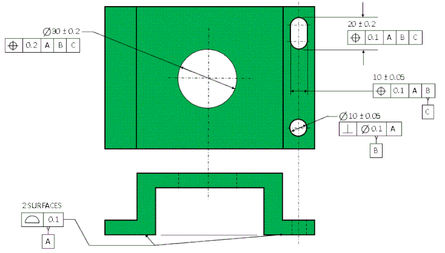
We see the datum scheme below. Since we want the cover to sit flat on our base, we make the flanges our primary datum feature. We control the form of both flanges (at the same time) with a profile tolerance.
We have constrained 3 degrees of freedom (1 translation and 2 rotations) with datum [A]. Now we create a net hole that will be barely larger than the bolt or the dowel pin that goes through it. We control the perpendicularity of this net hole relative to datum [A]. We label this net hole datum feature [B]. Datum [B] constrains two more translations.
We constrain the final rotation with a slot. The slot is the same width as datum feature [B]. The axis of the slot must go through the center of datum feature [B]. The tolerance of position on the width of the slot controls both the alignment to datum [B] and the perpendicularity to datum [A]. The width of the slot is designated as datum feature [C].
The length of the slot has a tolerance of position that controls the location of the slot relative to datum [B] and the orientation of the slot relative to datums [A] and [C].
Finally the large clearance hole has a tolerance of position that locates it relative to datums [B] and [C] and orients it relative to datum [A].
Any other features on the part could also be held relative to [A|B|C].


