Dimensioning For Function
The ASME Y14.5 standard states that "Dimensions shall be selected and arranged to suit the function and mating relationship of a part..."
This is an example of a part dimensioned according to function vs. dimensioned according to the manufacturing process.
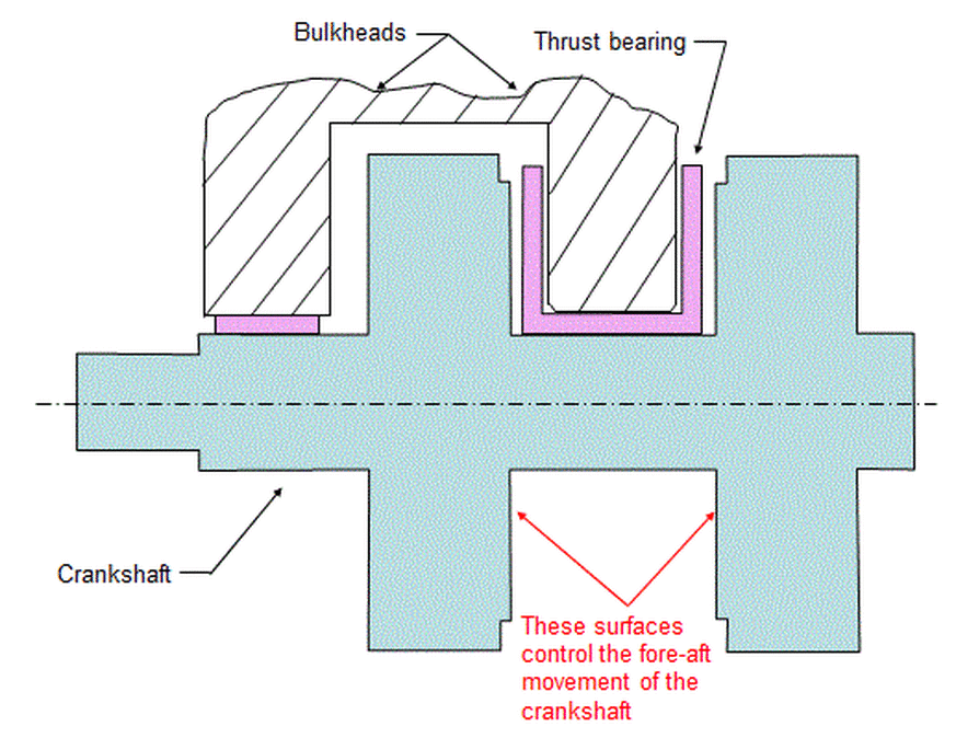
Consider the crankshaft as shown below. In the axial direction, the crankshaft is constrained by the bulkheads in the engine block through a thrust bearing.
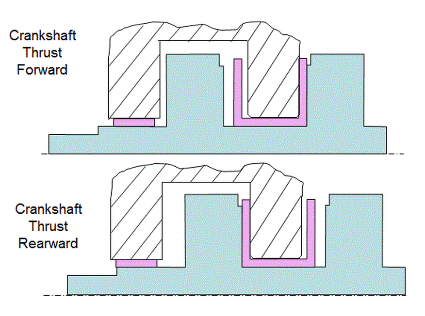
The figure below shows the crankshaft constrained by the bulkheads in its fore and aft positions.
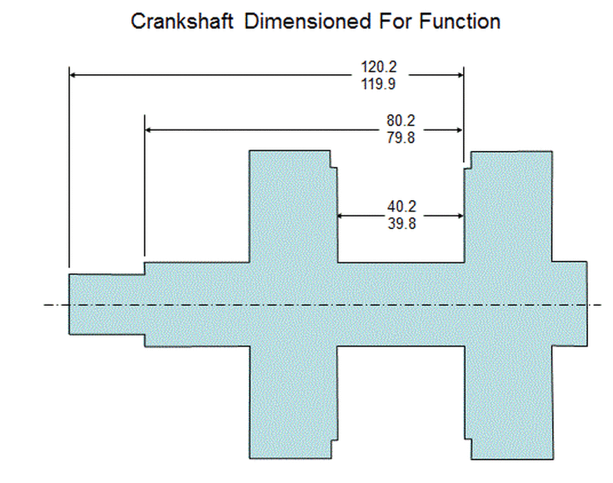
Since that crankshaft is constrained axially by its thrust surfaces pushing against the thrust bearing, it is those thrust surfaces that are the functional features for axial locations on the crankshaft. Therefore to dimension according to function, dimension all of the fore-aft cuts on the crankshaft relative to one of the thrust surfaces as shown below.
Dimensioning according to function, as indicated above, makes sense from a design perspective. However, manufacturing engineers tend to have a different point of view.
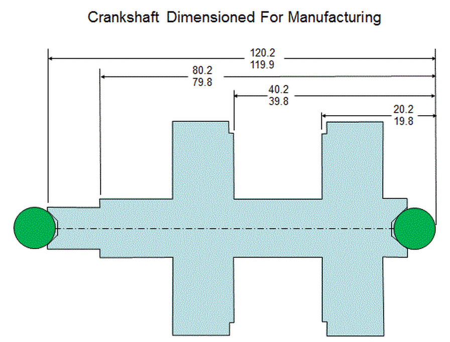
When the crankshaft is manufactured, centers are machined into the ends of the crankshaft. Gage balls are inserted into the centers, and the crankshaft is held by these gage balls while the axial cuts are being made. The manufacturer measures for all of its axial cuts from the rear of the rear gage ball. Therefore from a manufacturing standpoint, it makes more sense to dimension from the rear of the rear gage ball as shown below. Thus a conflict arises between the design engineer and the manufacturing engineer.
When the crankshaft is manufactured, centers are machined into the ends of the crankshaft. Gage balls are inserted into the centers, and the crankshaft is held by these gage balls while the axial cuts are being made. The manufacturer measures for all of its axial cuts from the rear of the rear gage ball. Therefore from a manufacturing standpoint, it makes more sense to dimension from the rear of the rear gage ball as shown below. Thus a conflict arises between the design engineer and the manufacturing engineer.
To resolve the conflict, consider the fact that the engine knows nothing of gage balls. It only knows about the thrust surfaces. Therefore the correct way to dimension the crankshaft is from the thrust surface. If manufacturing chooses to use gage balls, they are free to do that. However, the final product must meet the requirements of the engine. The manufacturer must meet the specs set up in the drawing with the axial cuts located from the thrust surfaces.


