Dimensioning Pipes
Pipes are often dimensioned in ways that do not make sense.
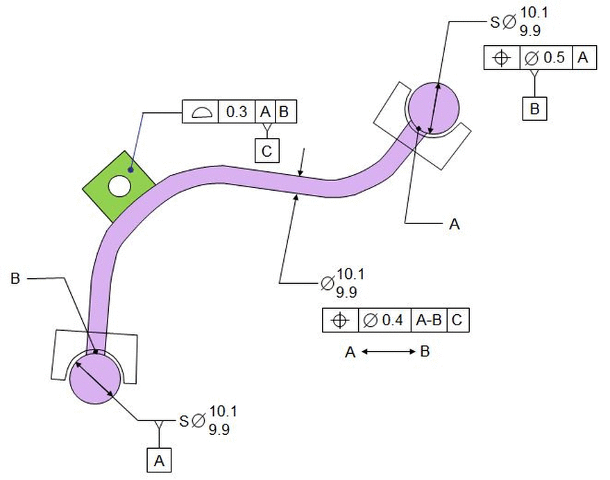
Below is an example of how to dimension high pressure pipes.
High pressure pipes will commonly have spherical ends surrounded by a threaded fitting. It is the spherical ends that locate the pipe in the machine along with a bracket attached to the pipe.
The spheres are labeled datum [A] and datum [B]. Datum [B] is located relative to datum [A] with the Tolerance Of Position. Since at this point there is no orientation, this Tolerance Of Position will control only the distance between the two spheres.
Datum [C] the surface of the bracket. It's located to the spheres . To understand how the bracket is located, imagine a fixture with spheres to hole [A] and [B] and a surface against which datum [C] must lie flat within the profile tolerance.
Finally the pipe itself is located relative to datums [A],[B], and [C]. The diameter of the pipe is called out, and a Tolerance Of Position locates the length of pipe between points A and B. Since both spheres contribute equally to locating the pipe, the datum reference is [A-B]. Note that the points A and B must not be confused with datums [A] and [B].
The drawing must also contain basic dimensions or a note saying that all dimensions for the pipe (whether they be from a chart or derived from the math model) are basic.
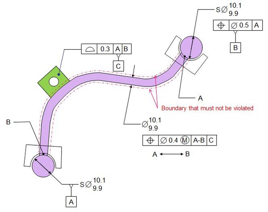
Also if you prefer to specify a fixed boundary that the pipe must not violate, you could call out the Tolerance of Position MMC as shown below. In this case the fixed boundary will be a 10.5 dia boundary.


