Dimensioning Symmetrical Widths
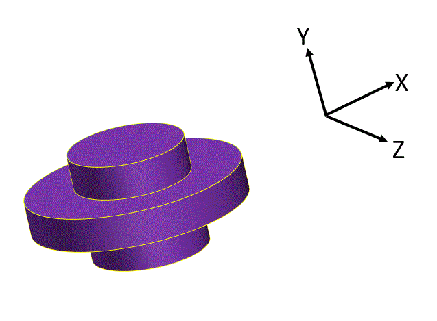
The part below has two widths that get sandwiched between parts.
The coordinate system shown will relate the three dimensional part to the subsequent two dimensional drawing views.
The coordinate system shown will relate the three dimensional part to the subsequent two dimensional drawing views.
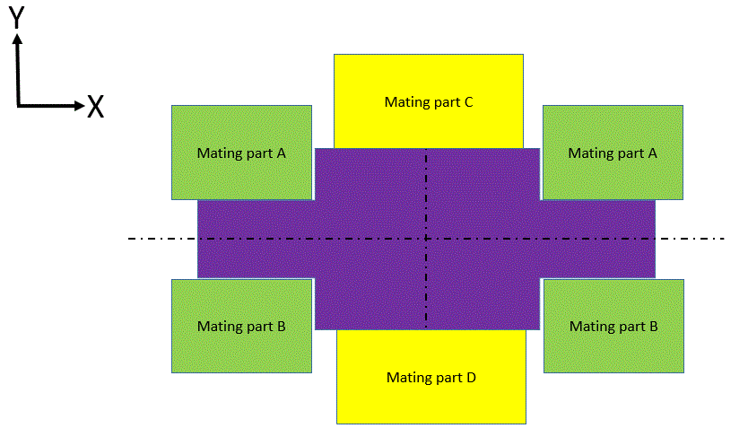
We can see below how the part functions. The thinner width gets sandwiched between parts A and B. The thicker width gets sandwiched between parts C and D. So the two widths function as features of size that are symmetrical with each other.
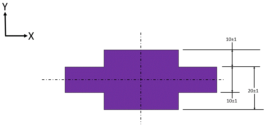
People are all too often tempted to dimension surfaces such as these with coordinate tolerances - just to get some dimensions on everything. But the coordinate tolerancing does not capture the way the part functions.
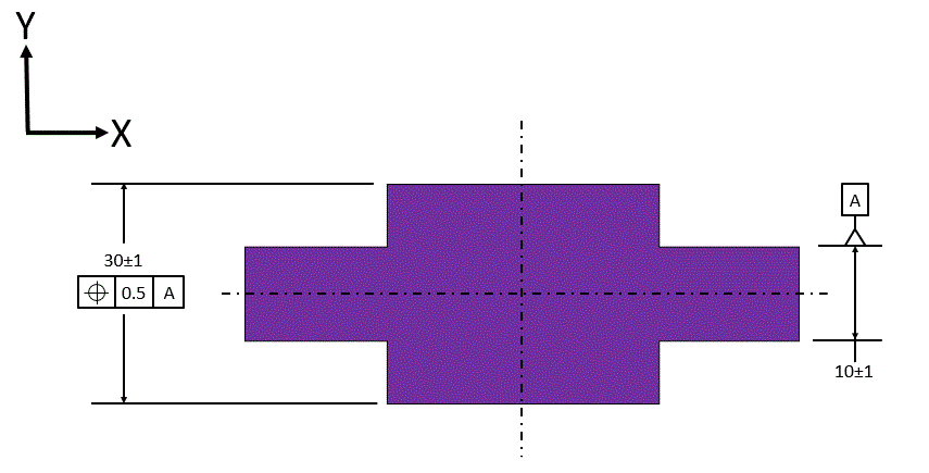
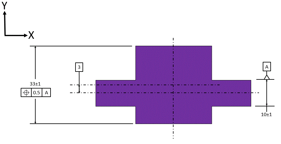
Here we see the part dimensioned the way it functions. The thinner width is datum feature [A]. Datum [A] is the center plane of this feature of size. We call out the size dimension, and we place the datum feature symbol in line with the size dimension.
The thicker width has its size called out, and it is located relative to datum [A] with a tolerance of position. Note that since the two widths are symmetric, there is an assumed basic dimension of zero between the center plane of the thicker width and datum [A].
The thicker width has its size called out, and it is located relative to datum [A] with a tolerance of position. Note that since the two widths are symmetric, there is an assumed basic dimension of zero between the center plane of the thicker width and datum [A].
Finally we can observe that if the two widths were not symmetrical, we would still dimension them the same way. The only difference is that the basic dimension now is no longer zero.

