Distance Between Holes
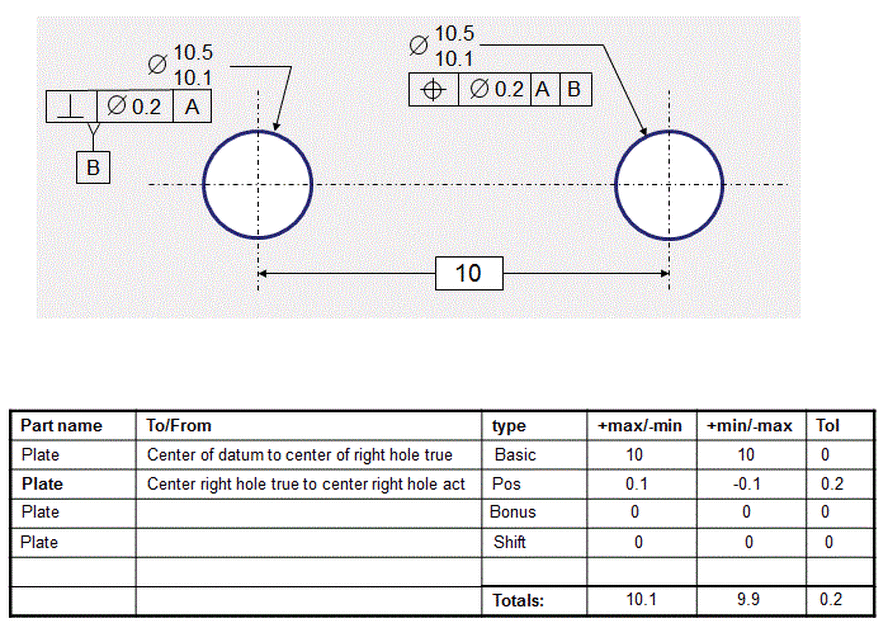
When dimensioning two holes that are located relative to each other, most people seem to automatically dimension them as shown below. One of the holes is designated as a datum, and the other hole is located relative to the datum hole. This works. However, it implies that the datum hole serves some function that the other hole does not.
Note the distance between the two hole centerlines as defined by the tolerance stack:
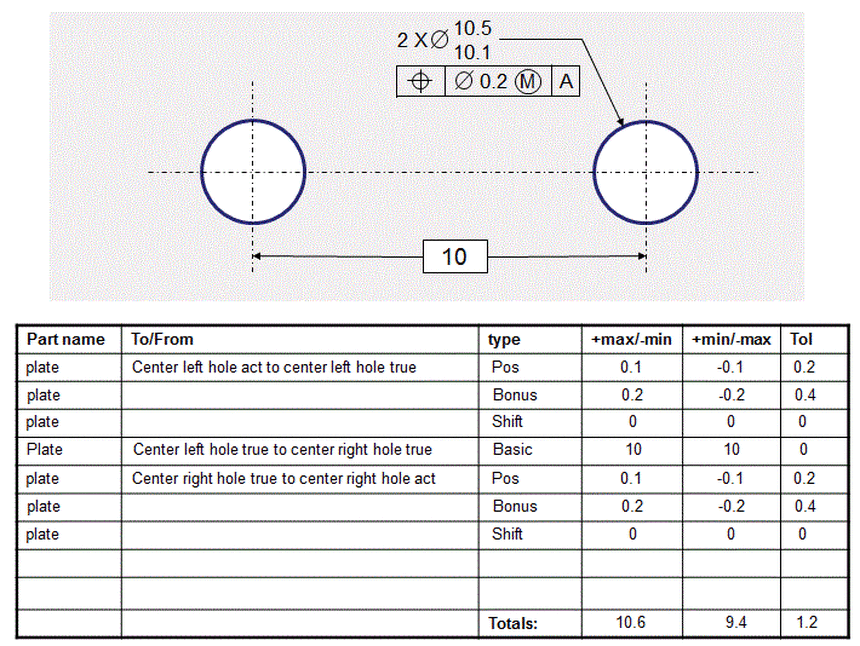
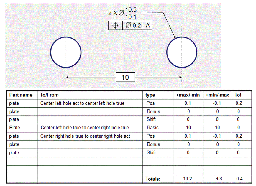
Usually the two holes functionally contribute equally to the function of the part. Therefore the appropriate functional way of dimensioning them is as a pattern as shown below.
Note that the distance between the centerlines, as indicated by the stack, is different that it is above. Always be careful to take that into consideration when specifying the tolerance.
Note that the distance between the centerlines, as indicated by the stack, is different that it is above. Always be careful to take that into consideration when specifying the tolerance.
Now look at what happens when the holes are called out with the MMC and MMB modifiers. First observe the distance between the centers when dimensioned as a datum and a hole related to the datum.
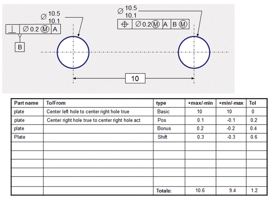
Now compare the above to the stack below when the two holes are called out as a pattern.