Pattern Datums
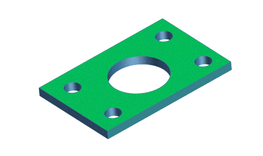
The plate below has a surface that mates to another part. The four small holes locate the plate to the mating part by going over studs protruding from the mating part. The plate will go over all four studs at the same time and then sit flat on the mating part.
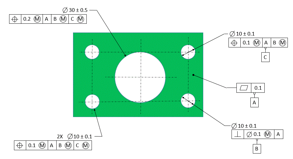
The figure below shows one possible datum scheme - one that is used all too often. The mating surface is designated as the primary datum feature. That much is good. But then the designer chooses one of the small holes to designate as datum feature [B] and another one to designate as datum feature [C]. The two remaining locating holes and the large center hole are then located to [A] primary, [B] secondary, and [C] tertiary. This datum scheme implies that the holes designated as datum features [B] and [C] are somehow more important than the others. Since the holes are called out MMC and MMB, this also introduces unnecessary datum feature shift.
The datum scheme simply does not reflect how the part functions. And most likely it does not reflect how the part will be inspected.
The datum scheme simply does not reflect how the part functions. And most likely it does not reflect how the part will be inspected.
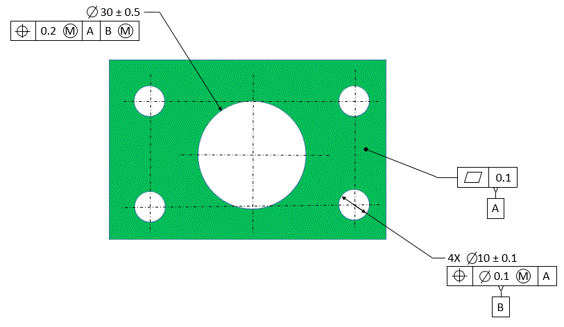
The better datum scheme, the one that reflects how the part functions and how it should be gaged, is shown below. All four locating holes are designated as pattern datum [B]. The large center hole is then located to [A] primary, and [B] secondary.
Everything is called out MMC and MMB because our only concern is assembly.
Everything is called out MMC and MMB because our only concern is assembly.


