Planar Datums
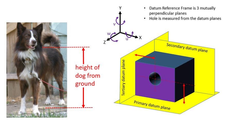
If we want to measure the height of a dog, we don't measure directly from the bottom of the dog's feet. The dog stands on the ground, and we measure up from the ground. The ground acts as a datum.
Consider some additional issues. First, the dog stands on four legs. All four feet touch the ground because the dog adjusts how he stands. But if we were to make a rigid statue of the dog and set it on a perfectly flat plane, we would never get all four feet to be in exactly the same plane. So the dog statue at any one time would rest on three of the four feet. It would rock. Likewise when measuring a part, if we set the part on a perfect plane, it will rest on the three high points. It might rock.
If we were to make a sheet metal statue of the dog, once again the four feet would never rest in the same plane at the same time. But since the sheet metal is non rigid, we may be able to force all four feet to rest on the plane by clamping them in place. This is frequently done with sheet metal parts or other non rigid parts. When this is done, there must be a note specifying exactly how the clamping is to be done so that the deformation will be exactly the same each time the part is measured.
Consider the part on the right side below. It's a block with a hole in it. We want to measure where the hole is, and we want the measurement to be repeatable. Our strategy is to set the block on and/or against three mutually perpendicular planes. Then we will measure from the planes. Note that we are measuring from the planes, we are not measuring directly from the sides of the block. The three mutually perpendicular planes are called a Datum Reference Frame.
In order to ensure that the measurement is repeatable, we not only specify that the part be set on and against the three datum planes, we also specify in which order to set the part against the datum planes. Because of imperfections in the part, we may get different answers if we were to push the part against the tertiary datum plane before the secondary datum plane instead of pushing it against the secondary datum plane before pushing it against the tertiary datum plane.
At this point we will also consider degrees of freedom being constrained. So the steps are:
First set the part on the primary datum plane. This will constrain the "Y" degree of freedom and also the "u" and the "w".
Second we push the part against the secondary datum plane. This will constrain the "Z" degree of freedom and also the "v".
Third we push the part against the tertiary datum plane. This will constrain the "X" degree of freedom.
Now the part is constrained in all six degrees of freedom. The measurement will be repeatable.
We specify the order of placing the part on the datum reference frame by using a Feature Control Frame. First we must identify which part features are related to which datums. We do this using Datum Feature Symbols.
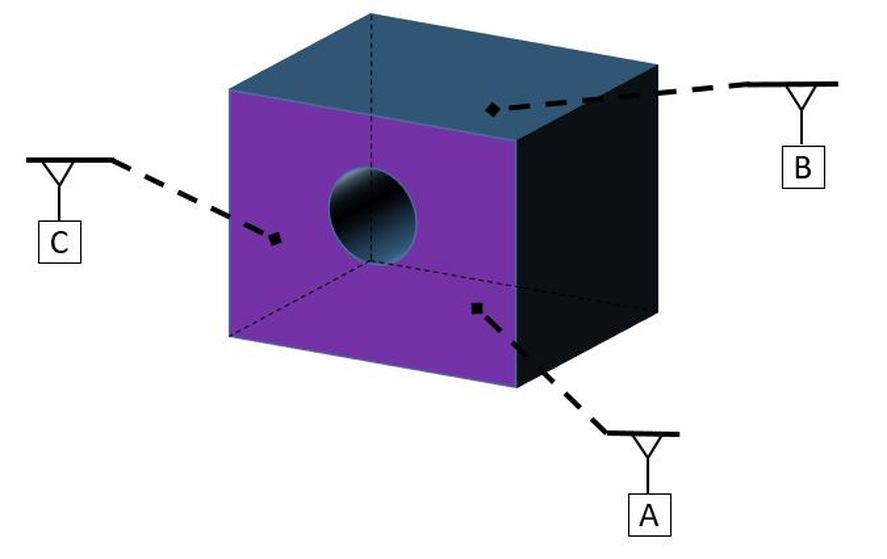
Datum feature symbols are the letters inside the boxes attached to plungers. In the figure below, they are attached to the part by leader lines. Note that the leader lines are all dashed. This is because the datum features are hidden features in this view. If the datum features were not hidden features, the leader lines would be solid.
In two dimensional drawings, datum feature symbols for planar datums are attached to a feature, an extension line, or a feature control frame.
Also note that datum features and datums are two different things. Datums are perfect, theoretical entities. In this section our datums are planes - perfect, theoretical planes. Of course, we cannot measure to perfect, theoretical planes. We must simulate the planes with gage fixtures or other physical things. The physical objects we use to simulate datums are called Datum Feature Simulators. Personally, I think they should be called Datum Simulators because they are actually simulating the datums. But the Y14.5 standard says that they are called Datum Feature Simulators.
So the things on the physical part are datum features. Datums are perfect planes (in this section). We cannot see or touch Datums. The physical objects that the Datum Features contact when measuring are Datum Feature Simulators.
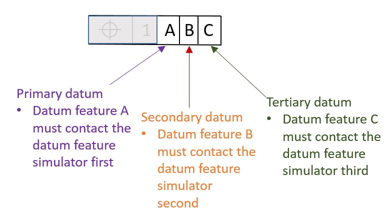
Now that we have our datum features established, we are ready to specify in which order to put them in contact with the Datum Feature Simulators. The Datum Feature Simulators must be contacted in the order stated in our Feature Control Frame. So per the Feature Control Frame below, datum feature A must contact the feature control frame first. Datum feature B must contact the feature control frame second. Datum feature C must contact the feature control frame third.
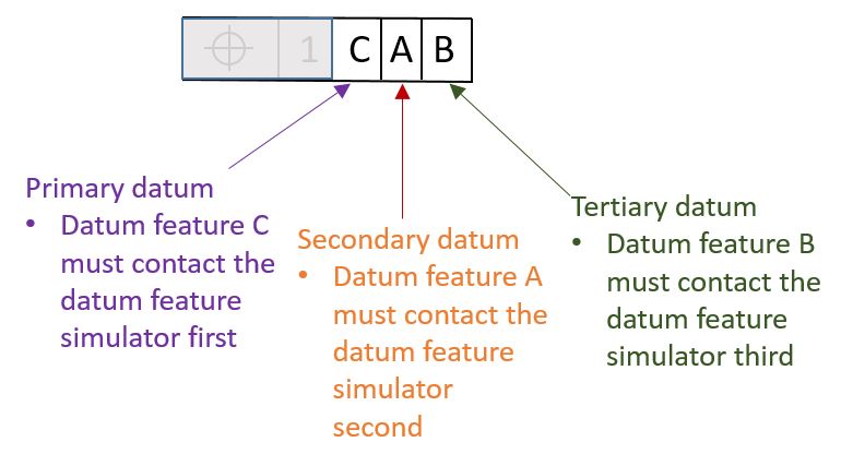
Note that the order we specify for contacting the Datum Feature Simulators does not need to be alphabetical order. It should be whatever makes sense based on the function of the part. So for instance there may be a circumstance in which the function of the part dictates that datum feature C should touch the Datum Feature Simulator first, then datum A, and then datum B. In that case we would specify our datums in our Feature Control Frame as shown below.