Runout
Runout comes in two flavors - circular runout and total runout.
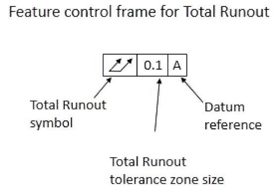
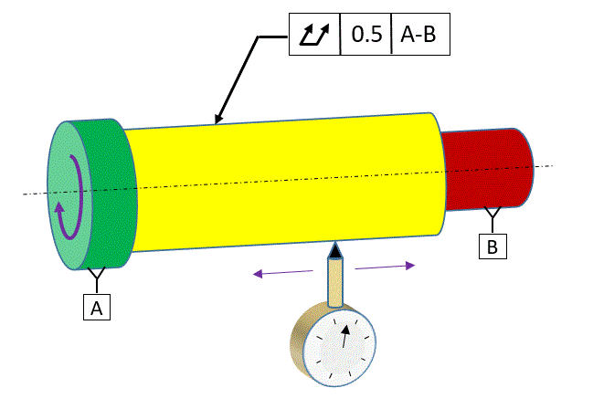
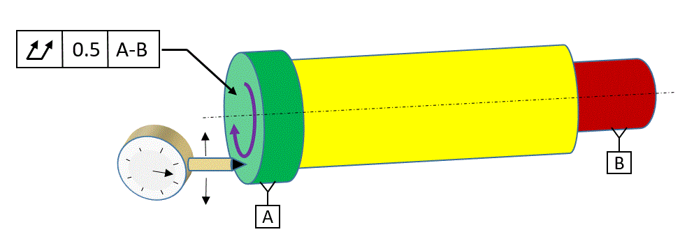
The feature control frame for Total Runout is shown below:
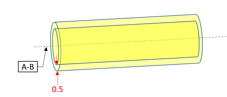
The feature control frame for Total Runout is shown below:
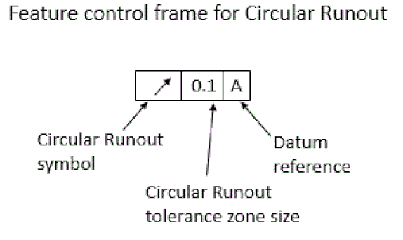
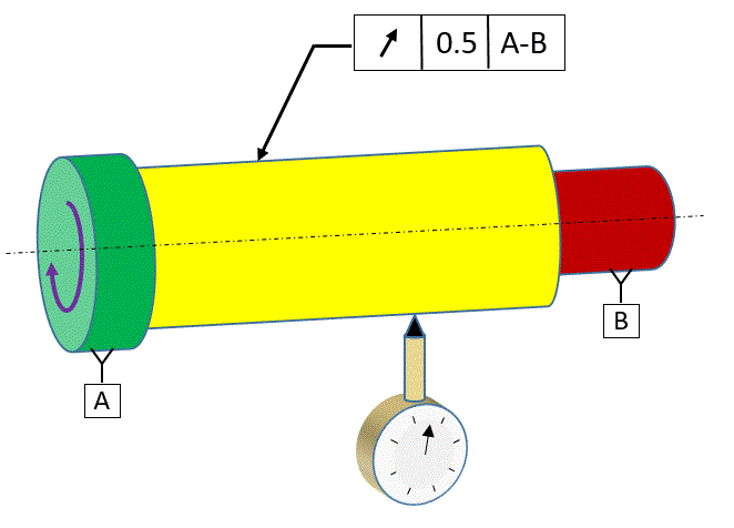
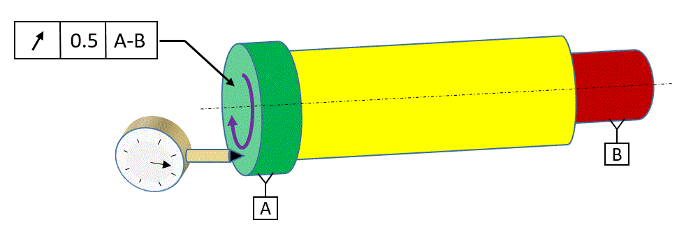
The feature control frame for Circular Runout is shown below:
We will illustrate what circular and total runout are all about and what their tolerance zones are by applying them to the housing of a laser pointer. A laser pointer can be used to keep your dog entertained by shining the dot on the floor or the wall in front of the dog and having the dog chase it.
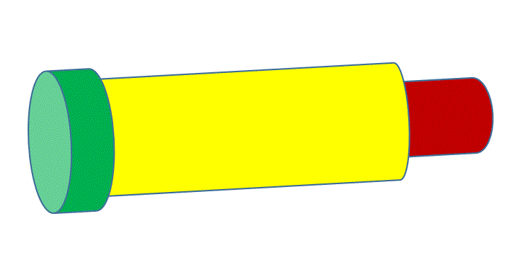
Our laser pointer has three cylinders. The yellow cylinder contains the battery. The green cylinder is removable to gain access to the battery compartment. The red cylinder contains the light bulb.
Our laser pointer has three cylinders. The yellow cylinder contains the battery. The green cylinder is removable to gain access to the battery compartment. The red cylinder contains the light bulb.
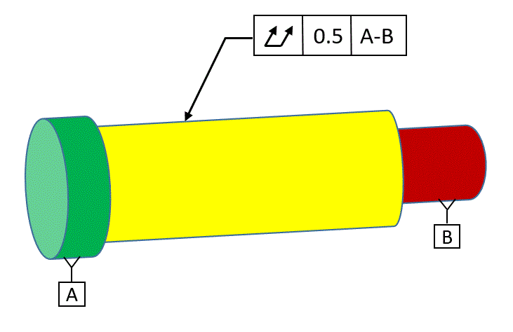
We will define the green cylinder and the red cylinder as datums and specify total runout on the yellow cylinder relative to the two datums.
When we measure runout, we rotate the part about a datum axis. In this case, we will rotate the part about the axis that goes from datum [A] to datum [B].
When we measure runout, we rotate the part about a datum axis. In this case, we will rotate the part about the axis that goes from datum [A] to datum [B].
The figure below shows how we would gage this total runout callout. While rotating the part around axis [A-B], we put our dial indicator against the surface and move the dial indicator back and forth as we rotate the part. The intention is to have the dial indicator measure all points on the surface (or as many as we can reasonably get). The full indicator movement of the dial indicator (max to min) is the total runout error. This must be less then the total runout tolerance value in order for the part to be within spec.
The figure below shows the tolerance zone for our total runout tolerance. The tolerance zone is the space between two coaxial cylinders centered about the datum axis. The radial distance between the cylinders is equal to the runout tolerance value. The total runout tolerance controls cylindricity of the part plus location and orientation of the surface relative to the datum axis. Runout does not care about the size of the part.
Now we will apply a Circular Runout tolerance to the surface instead of Total Runout. The part is rotated about the datum axis just as with total runout. But now the dial indicator is held still while the part is being rotated. The full indicator movement of the dial indicator is the circular runout at that particular cross section of the part.
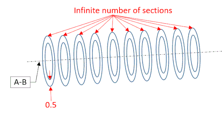
The person gaging the part is responsible to repeat this process at each of an infinite number of cross sections.
The person gaging the part is responsible to repeat this process at each of an infinite number of cross sections.
The tolerance zone is two concentric circles at each cross section, centered about the datum axis.
The circular runout callout controls circularity and location and orientation of the surface relative to the datum axis.
So why would one choose to specify circular runout instead of total runout? Circular runout is easier to measure, and circular runout can be applied to a surface that is not a cylinder. For instance, circular runout could be applied to a cone.
Note that when applying circular runout to a surface that is not a cylinder, the dial indicator is supposed to be held at an angle that is normal to the surface for any given cross section.
Runout can also be measured on a surface that is perpendicular to the datum axis. The figure below shows total runout being measured. The dial indicator is moved up and down on the surface as the part is rotated around the datum axis. Theoretically the dial indicator will contact all points on the surface.
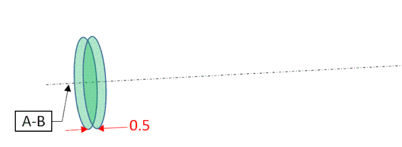
The tolerance zone is two parallel planes that in this case are 0.5 apart and exactly perpendicular to the datum axis. This tolerance zone will control the perpendicularity and the flatness of the surface. It will not control location.
We can also measure circular runout of the surface that is perpendicular to the datum axis. The dial indicator is held stationary while the part is rotated around the datum axis. Once the reading is taken, the dial indicator is moved radially and then the part is rotated again. This is repeated for theoretically an infinite number of radii from the datum axis.
The tolerance zone is two circles for each of the radii where a measurement was taken. So there should theoretically be an infinite number of these pairs of circles. Each of the pairs is 0.5 apart in this case.
Circular runout applied to this surface will control perpendicularity but not flatness. Each of the pairs of circles is independent of the others, so the location could be different at one radius than it is at another radius.
Circular runout applied to this surface will control perpendicularity but not flatness. Each of the pairs of circles is independent of the others, so the location could be different at one radius than it is at another radius.
Note that runout is a surface control, not a feature of size control. So the MMC and LMC modifiers are not allowed with runout.

