A Stack That Requires Trigonometry
This stack is similar to one that I performed in industry. The stack illustrates two concepts - first, it shows how a stack can use trigonometry. Second, it shows the power of appropriate dimensioning to reduce the variation in the tolerance stack.
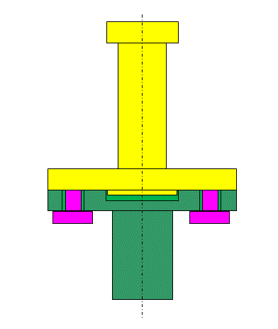
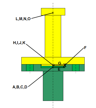
Consider the assembly below. The boss on the bottom of the yellow part pilots into the hole in the top of the green part. The clearance between the bolts and the holes is large enough that the bolts do not locate the yellow part in the green part. Location is done by the boss piloting in the hole.
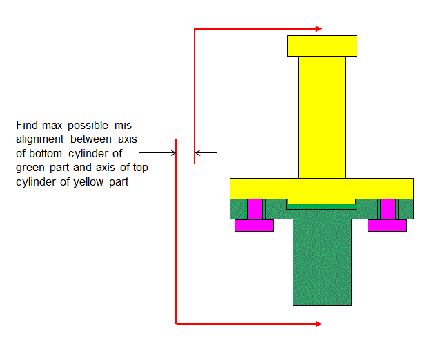
The stack asks for the maximum offset between the axis of the bottom cylinder of the green part and the axis of the top cylinder of the yellow part.
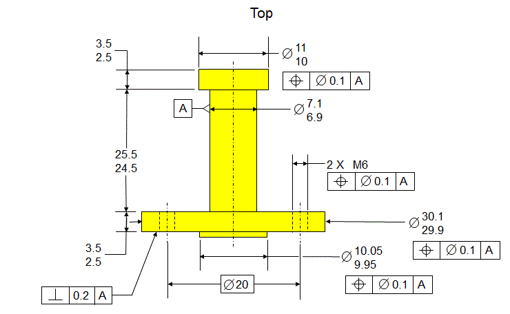
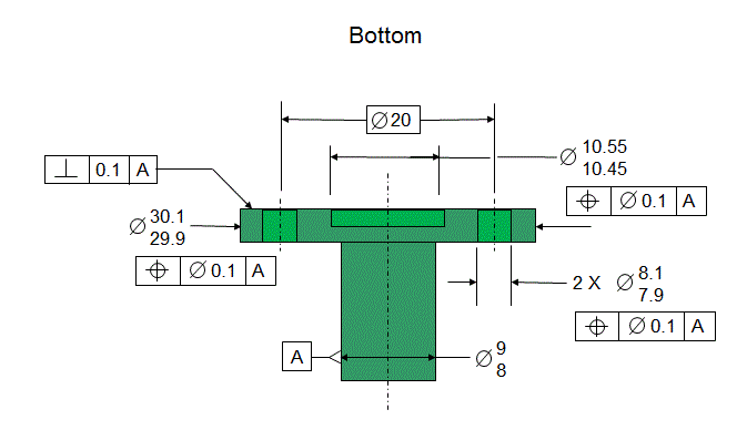
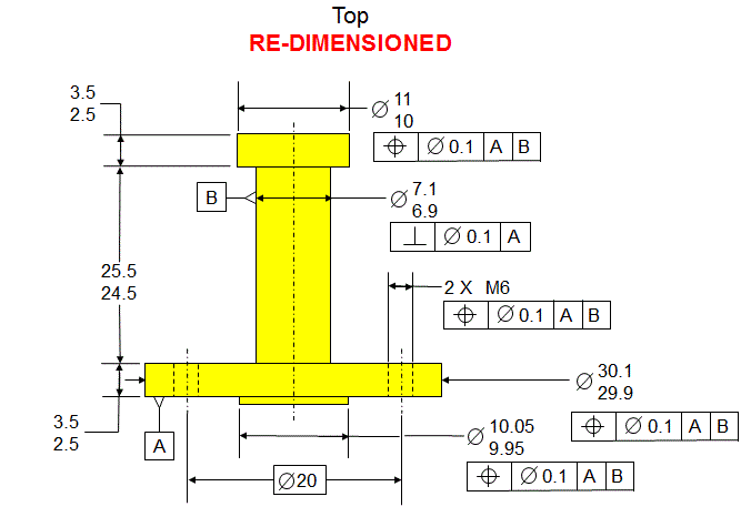
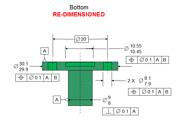
The parts are dimensioned as shown below
The stack will first be done ignoring the Perpendicularity tolerances. Then the effects of the Perpendicularity tolerances will be calculated and included in the stack.
The stack path, ignoring the Perpendicularity, is shown below. The path is:
Datum [A] in green part to center of pilot hole true
Center of pilot hole true to center of pilot hole actual
Bonus
Shift
Center of pilot hole actual to Right Side of pilot hole
Right side of pilot hole in green part to Right side of boss in yellow part
Right side of boss to center of boss actual
Center of boss actual to center of boss true
Bonus
Shift
Center of boss true to datum [A]
Datum [A] to center or top cylinder true
Center of top cylinder true to center of top cylinder actual
Bonus
Shift
Below is the stack
Now consider the effects of perpendicularity.
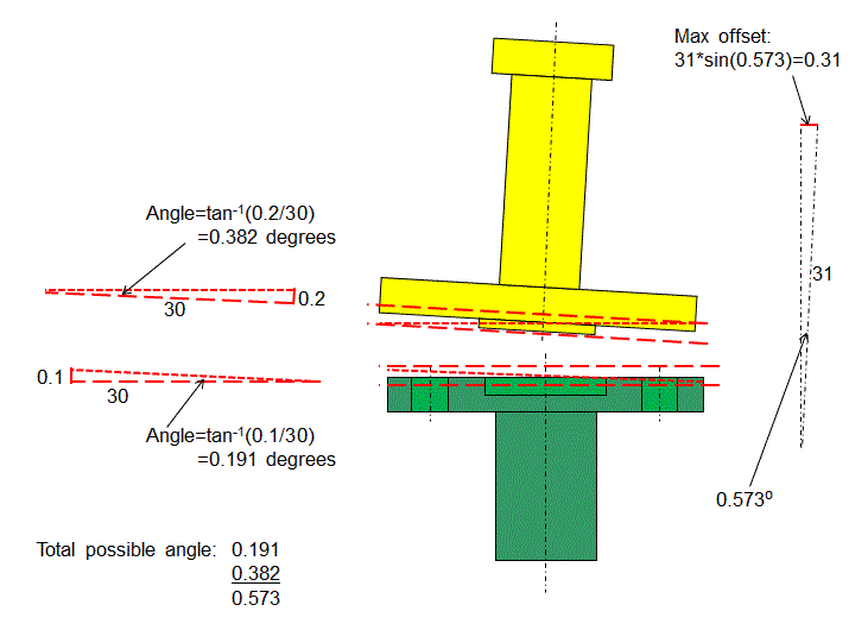
In each part, the surface with the Perpendicularity tolerance must fall between two parallel planes that are the distance apart specified by the Perpendicularity tolerance.
The diameter of the surface and the magnitude of the perpendicularity tolerance provides the lengths of the legs of the triangle. This enables the angle of the triangle to be found.
Add the two angles to get the total angle that the axis of the yellow part could deviate from the axis of the green part.
On the far right, this total angle and the total height of the yellow part provide the angle and the hypotenuse for the triangle. The leg at the top of the triangle is the amount that the axis of the top cylinder of the yellow part could be offset from the axis of the green part due to the perpendicularity tolerance.
Note that the nominal height of the yellow part was used. It was assumed that the tolerance in the heights of the yellow part will not significantly affect the results of the stack.
Now the results of the Perpendicularity are added into the stack.
Note that since the side of the boss was grounded against the side of the pilot hole, the 0.76 value is the relevant value and the -0.26 value is not relevant.
Now consider what happens if we re-dimension the parts as shown below.
Now consider what happens if we re-dimension the parts as shown below.
Now in both the green and yellow parts, datum [B] is defined as being perpendicular to datum [A]. The diameters that are located relative to [A] primary and [B] secondary are defined such that their axis must fall within tolerance cylinders that are perfectly perpendicular to datum [A]. Therefore the geometric effect from the Perpendicularity tolerances is no longer there. Therefore the stack is as shown below:
Note that since that side of the boss in the yellow part is grounded against the side of the pilot hole in the green part, the 0.45 value is relevant and the 0.05 value is irrelevant.

