Modifiers
This page provides a concise, quick reference for the modifiers. Many of them will be expanded upon in other areas of the text.
Maximum Material Condition (MMC) is the size of a feature of size for which the part contains the maximum amount of material. For an internal feature of size, the MMC size is the smallest allowable size. For an external feature of size, the MMC size is the largest allowable size.
When the MMC modifier is used, it indicates that the specified tolerance applies when the feature of size is at the MMC size. As the size of the feature of size departs from the MMC size, the tolerance is increased by the amount that the size departs from the MMC size.
When the MMC modifier is used, it indicates that the specified tolerance applies when the feature of size is at the MMC size. As the size of the feature of size departs from the MMC size, the tolerance is increased by the amount that the size departs from the MMC size.
Maximum Material Boundary (MMB) is a boundary that the datum feature of size will not violate. The MMB is calculated by combining the MMC size with any applicable geometric tolerance on the datum feature of size. The MMB is always outside the material.
The figure below shows one example of a Maximum Material Boundary
The figure below shows one example of a Maximum Material Boundary
Below is an example of MMC and MMB for an external Feature of Size. The MMC size is the largest size, and the MMB is the boundary perpendicular to datum [A]. The diameter of the MMB is equal to the MMC size plus the Perpendicularity tolerance.
Least Material Condition (LMC) is the size of a feature of size for which the part contains the minimum amount of material. For an internal feature of size, the LMC size is the largest allowable size. For an external feature of size, the LMC size is the smallest allowable size.
When the LMC modifier is used, it indicates that the specified tolerance applies when the feature of size is at the LMC size. As the size of the feature of size departs from the LMC size, the tolerance is increased by the amount that the size departs from the LMC size.
When the LMC modifier is used, it indicates that the specified tolerance applies when the feature of size is at the LMC size. As the size of the feature of size departs from the LMC size, the tolerance is increased by the amount that the size departs from the LMC size.
Least Material Boundary (LMB) is a boundary that the datum feature of size will not violate. The LMB is calculated by combining the LMC size with any applicable geometric tolerance on the datum feature of size. The LMB is always inside the material.
The figure below shows one example of a Least Material Boundary
The figure below shows one example of a Least Material Boundary
Below is an example of LMC and LMB for an external Feature of Size. The LMC size is the smallest size, and the LMB is the boundary perpendicular to datum [A]. The diameter is equal to the LMC size minus the Perpendicularity tolerance.
The datum translation symbol is the triangle shown in the far right box of the feature control frame above. It indicates that the datum feature simulator for the [F] datum is free to translate.
Consider the figure above. When gaging the pattern of four holes, the part is intended to be constrained at [A], [E], and [F]. Datum [A] is intended to take out the translation in the Z direction and the rotations about the X and Y axis. Datum [E] is intended to take out the translations in the X and Y directions. Datum [F] is intended to take out only the rotation around the Z axis.
If the part is gaged with two round pins at [E] and [F], then the gage will treat these two holes equally. Both holes together will take out the translations in the X and Y and the rotation around the Z.
The datum translation symbol allows a gage to be used that has pins for both holes [E] and [F] with the pin for hole [F] being free to translate. With [F] free to translate, hole [E] will take out the translations in the X and Y directions and hole [F] will take out only the rotation about the Z axis. Thus the part will be constrained exactly as intended by the feature control frame.
In the diagram below, if there were no modifier on the callout for datum [C], the datum simulator would be within the range specified by the profile tolerance, wherever it can make maximum contact with the datum feature.
With the [BSC] modifier, the datum feature simulator is fixed at the basic location of datum [C].
With datum [C] called out MMB, the datum feature simulator is at the MMB location of the datum feature. The MMB location is calculated by adding the basic dimension 20 and half the profile callout.
The figure below shows an angularity callout. Angularity requires that the surface be between two parallel planes that are 2 millimeters apart and exactly 20 degrees from datum [B].
The figure below shows that this particular surface fails the requirement because it falls outside the planes.
In the figure below, the tangent plane modifier is used. Now the requirement is met because a plane tangent to the surface fits between two parallel planes that are 2 millimeters apart and 20 degrees from datum [B].
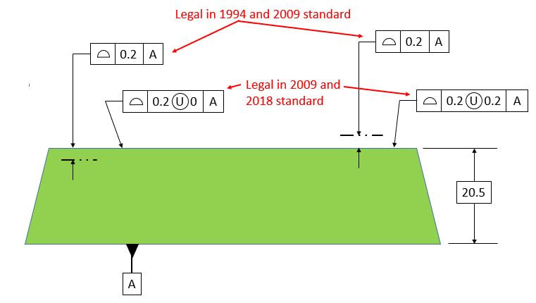
The profile tolerance defaults to equally disposed about the true profile. Sometimes it may be desirable to have the tolerance zone unequally disposed about the true profile. In previous versions of the standard, a basic dimension to a phantom line indicated the tolerance zone. This method is still legal in the 2009 standard but not in the 2018 standard. In the 2009 or 2018 standard, one can use the U in a circle as indicated below. The number immediately following the unequally disposed symbol indicates the amount of tolerance outside the material.
The 2009 standard permits the use of a profile boundary that is any shape required by the user. The Non Uniform Boundary is shown below. The boundary is described by basic dimensions and phantom lines. In the figure below, the solid line represents the true profile.
The Tolerance Of Position requires that the axis of the dowel hole be contained within the 0.2 dia tolerance cylinder.
The Tolerance of Position requirement mentioned above allows the dowel hole, and therefore the dowel, to tilt within its tolerance zone. If there is a cover as shown below, a conflict can occur between the dowel and the cover. The same situation applies to a threaded hole with a bolt that must clear a hole in the cover.
The Projected Tolerance Zone modifier brings the tolerance zone above the part as shown below. The number following the modifier specifies how high above the part the tolerance zone must project. Usually this number corresponds to the thickness of the mating part.
With the axis of the hole (and therefore the pin) inside the projected tolerance zone, the conflict is gone.
The standard says: "Statistical Tolerancing is the assigning of tolerances to related components of an assembly on the basis of sound statistics" It goes on to list some examples. However, when you just put the symbol on a drawing, it does not specify specifically which statistical tools must be used. Therefore it is ambiguous, and I always recommend that people not use it. If you want to specify a statistical requirement on a drawing, you should explicitly state what the requirement is.
The Free State symbol is used when the part is constrained with a general constraint note. Tolerances that must be measured in the free state (exceptions to the general constraint note) are called out with the Free State symbol in the Feature Control Frame.
The independency symbol overrides rule #1.
Recall that rule #1 specifies a boundary that a Feature of Size is not allowed to violate. In the top row of the diagram below, the Feature of Size has a boundary 11 wide that it is not allowed to violate. If the part is made at 11, it must be perfectly straight. If it is made between 10 and 11, it can be bowed as long as the part does not violate the 11 boundary.
In the bottom row, the Independency symbol is used. The part must still be between 10 and 11 wide at any given point. However, now the part can be 11 wide and still be bowed. As it is specified below, there is no limit to how much the part can be bowed. It is adviseable to include some other way of limiting the flatness error when overriding rule #1 with the independency symbol.
Below are the two most common uses for Continuous Feature.
First, Continuous Features is used on the bottom surface of the rectangular part. With the CF modifier, the flatness applies to the entire bottom surface of the part as if it did not have the slot.
In the second case, with the CF applied to the cylinder, rule number 1 applies as if it were all one cylinder.
|
In the figure below, the between symbol indicates that the profile tolerance applies between point D and point E. There are two different paths to go from point D to point E. The profile tolerance applies to the path where the arrow is pointing.
The all around symbol indicates that the profile tolerance applies all around the shape in this view.
The all over symbol indicates that the profile tolerance applies to every surface of the part. Note that in this case, no datums are specified. The part should be suspended in space and compared to the 3-D CAD model. The most common application for this symbol is castings in their as cast condition.
"Boundary" indicates that the geometric tolerance is protecting a boundary. It is normally used in conjunction with the MMC modifier. However, when using the MMC modifier, it is normally understood that a boundary is being protected anyway. Therefore this term tends to be redundant.
This is used with orientation tolerances. The term "Each Element" specifies that the tolerance applies to individual line elements rather than the whole surface at once.
This is used with orientation tolerances. It specifies that the tolerance applies to radial elements as shown below.