
Profile
Profile comes in two flavors - profile of a surface and profile of a line.
The feature control frame for Profile of a surface is shown below:
The feature control frame for Profile of a surface is shown below:
The feature control frame for Profile of a line is shown below:
For most applications, profile of a surface is the appropriate callout. So we will first look at profile of a surface. Then we will introduce profile of a line and contrast the two.
Profile is an extremely versatile control. In fact, some people advocate discontinuing all of the other controls and using profile for everything. However, as versatile as profile is, the other controls have their place. They allow us to do things such as bonus and datum feature shift and projected tolerance zones. The controls all work together to ultimately meet our specific needs.
Profile can control, form, location, orientation, and size or any subset of these. Profile can be used with or without datum references and with or without basic dimensions. We will cover all of these applications.
First we will look at how profile can control form. Actually profile always controls form. We will begin by looking at applications in which profile controls only form. Profile is always applied to a surface, so profile can control the form of a surface. Profile cannot control the form of a derived median line or a derived median plane of a feature of size.
We have seen flatness called out on a surface as on the left in the figure below. We can get the same result by using profile with no datum callouts as on the right.
In both cases the tolerance zone is two parallel planes that are 0.1 apart as shown below.
One of the places that profile is often used to control flatness is when flatness must be controlled on multiple surfaces. Flatness can only be applied to one surface at a time unless the Continuous Feature symbol is used to indicate that the two surfaces must be considered to be one surface. It is common to use profile and indicate that the profile tolerance applies to both surfaces. Both of the figures below have exactly the same interpretation.
Below is the tolerance zone that applies to both of the figures above. In both cases, both surfaces must fit within a common tolerance zone made up of two parallel planes that are 0.1 apart.
If profile of a surface is applied to a cylinder, it can control size and cylindricity. And cylindricity by default controls straightness and circularity.
In the figure below, the size is controlled by the size tolerance. The profile of a surface callout controls cylindricity. Regardless of whether the pin is manufactured at 9 dia or 11 dia or anywhere in between, the entire surface must fall between two coaxial cylinders that are 0.1 apart. The sizes of the cylinders can vary depending on the size of the pin that is being manufactured.
In the figure below, the size is controlled by the size tolerance. The profile of a surface callout controls cylindricity. Regardless of whether the pin is manufactured at 9 dia or 11 dia or anywhere in between, the entire surface must fall between two coaxial cylinders that are 0.1 apart. The sizes of the cylinders can vary depending on the size of the pin that is being manufactured.
Now we have a basic diameter specified on the cylinder. Therefore the profile of a surface callout controls size as well as cylindricity. The entire surface must still fall between two coaxial cylinders 0.1 apart. However, now one of those cylinders has a fixed diameter of 10.1 and the other has a fixed diameter of 9.9.
It's time to introduce the term "True Profile". True Profile is the size and shape of the part as described by basic dimensions. For the pin below, the true profile has a basic diameter of 10. The profile tolerance tells us how far we are allowed to depart from the true profile.
It's time to introduce the term "True Profile". True Profile is the size and shape of the part as described by basic dimensions. For the pin below, the true profile has a basic diameter of 10. The profile tolerance tells us how far we are allowed to depart from the true profile.
The dog biscuit below also has a true profile that is defined by basic dimensions. The basic dimensions are not shown because we expect the user to derive the basic dimensions from the CAD model. This is an acceptable practice. It requires specifying in a note on a drawing or in some other document that basic dimensions are to be derived from the CAD model.
Once again we have a profile tolerance without a datum reference. The tolerance points to a surface, and it has a circle at the knee of the arrow. That circle is the 'all around" symbol. The all around symbol tells us that the tolerance applies all around the part, but only in one view.
Once again we have a profile tolerance without a datum reference. The tolerance points to a surface, and it has a circle at the knee of the arrow. That circle is the 'all around" symbol. The all around symbol tells us that the tolerance applies all around the part, but only in one view.
The tolerance zone is shown below. The tolerance zone is centered on the true profile, and it goes all around the part in this view. Without the all around symbol, the extent of the tolerance zone would default to just the segment to which the arrow is pointing. The tolerance zone would end at the tangent points of the radii at the corners of the dog biscuit.
The profile tolerance in the figure below has a double circle at the knee of the arrow. The double circle is the "all over" symbol. This means that the profile tolerance applies all over the entire part in all directions.
The tolerance zone for the all over symbol is shown below. We can think of the tolerance zone as being the space between a smaller dog biscuit inside our true dog biscuit and a larger dog biscuit outside our true dog biscuit. At any given point, the smaller dog biscuit and the larger dog biscuit in this case are 0.1 apart and centered on the true dog biscuit.
This is a common practice with castings. No datums are called out. The part virtually hangs in space, and each point on the part is compared to the corresponding point on the CAD model to see whether or not it is within the tolerance zone.
This is a common practice with castings. No datums are called out. The part virtually hangs in space, and each point on the part is compared to the corresponding point on the CAD model to see whether or not it is within the tolerance zone.
All of our examples so far have had the tolerance zone half inside the part and half outside the part. This is called "Equal Bilateral." Now we will look at a way to specify the tolerance such that the tolerance zone is not equally divided inside and outside the material. This is proving to be a quick and easy way to slightly adjust the location of the tolerance zone without having to change the CAD model. The Unequally Disposed symbol is a U inside a circle that is inserted into the feature control frame.
We will demonstrate the Unequally Disposed symbol using an example of the area in which a dog poops. Consider the dog's yard to be the part. The neighbors' yards are outside the part. The poop zone represents the profile tolerance zone that we wish to apply to the part.
The default tolerance zone is equal bilateral. In this case, Spot poops in an area that is five feet wide, 2.5 feet into his own yard and 2.5 feet into the neighbors' yards.
Spot's neighbors don't like having Spot poop in their yards. They would prefer that he poop all in his own yard. This situation is specified by the unequally disposed symbol in the feature control frame below. The U in a circle is followed by a number that indicates how much of the tolerance zone is outside the material. In this case, there is a zero after the unequally disposed symbol. Therefore none of the tolerance zone is outside the material. It is all inside the material. So the poop zone extends 5 feet into Spot's yard and not at all into the neighbors' yards.

Spot knows that he should poop only in his own yard. However, as he becomes a little less disciplined, he follows the specification below. There is a 2 following the unequally disposed symbol. Therefore, the 5 foot wide poop zone is 2 feet into the neighbors' yards and three feet into Spot's yard.

As Spot becomes increasingly bold, he follows the control below with a 3 following the unequally disposed symbol. Now the poop zone is 3 feet into the neighbors' yard and only 2 feet into Spot's yard.
Finally Spot does what his owner has secretly wanted all along. He follows the control below with a 5 after the unequally disposed symbol. Now the poop zone is completely in the neighbors' yards and not in Spot's yard at all.
Profile can also act as an orientation control. The figure below on the left has two perpendicularity controls. The figure on the right has two profile controls. The profile controls in the figure on the right have exactly the same meaning as the perpendicularity controls in the figure on the left.
How do we know that the profile controls have the same meaning as the perpendicularity controls? We know that they will hold the surface between two parallel planes that are 0.2 apart just as the perpendicularity controls do. The profile controls also have datum references. All of the datums referenced are perpendicular to the surface being controlled. So the tolerance zone must be perpendicular to the datums referenced. Thus the profile controls have exactly the same meaning as the perpendicularity controls.
Note that we could also have chosen to replace the flatness control with a profile, and it would have the same meaning since profile with no datum reference always controls form.
|
|
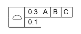
Now we will replace both perpendicularity and parallelism controls with profile controls. The profile control in the figure on the right has exactly the same meaning as the parallelism control in the figure on the left. But now we must be careful. The width of the dog house is controlled by the coordinate tolerance. Therefore the profile control controls orientation but not location. If the 22 dimension were a basic dimension, then the profile tolerance would control location as well as orientation.
|

|
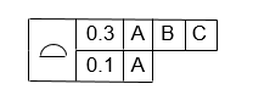
As it is, the location is controlled by the coordinate tolerance. The the wall can be anywhere between 21.85 and 22.15. Within this tolerance zone, the parallelism defines a 0.1 wide tolerance zone that floats within the 0.3 wide tolerance zone. The 0.1 wide tolerance zone controls the form and orientation of the wall.
If we have a basic dimension to the surface instead of a coordinate dimension, then the profile tolerance controls the location as well as the orientation and form.
Now the 0.1 wide tolerance zone is fixed and centered on the basic dimension. So the maximum width of the dog house is limited to 22.05 and the minimum is 21.95.
Note also that since the feature control frame references datum [B] and not [A], the 0.1 wide tolerance zone is exactly parallel to datum [B] and will almost never be exactly perpendicular to datum [A].
Note also that since the feature control frame references datum [B] and not [A], the 0.1 wide tolerance zone is exactly parallel to datum [B] and will almost never be exactly perpendicular to datum [A].
Profile can also be both multiple single segment and composite.
If you buy a bag of "GD&T CHOW" brand dog food, they will provide you with a cup that you can use to measure out how much food to give your dog. The amount of food that you give your dog will depend on the size of your dog. There are markings on the cup to show you how much food to give the different breeds of dog.
The functional requirements of the labels on the cup are:
For the "GD&T CHOW" label, location is not critical. However, in order to have it look nice, the orientation of the label (parallelism to datum [A]) is critical.
For the labels showing the different breeds, location in the horizontal direction is not critical. But location in the vertical is critical because that determines how much food the dog will get.
For the "GD&T CHOW" label, we choose a composite profile tolerance with the all around symbol. The top line will locate the label within a 0.5 tolerance zone all around. The bottom line will not locate. It will orient the label within a 0.2 tolerance zone relative to datum [A]. The bottom line will also tighten up the form within a tolerance zone of 0.2.
For the labels showing the different levels of dog food, we use a multiple single segment profile all around. In multiple single segment, both lines will locate to their respective datums. This will locate the label within a 0.5 tolerance zone horizontally and vertically, but it will tighten up the location to 0.2 relative to datum [A].
For the labels showing the different levels of dog food, we use a multiple single segment profile all around. In multiple single segment, both lines will locate to their respective datums. This will locate the label within a 0.5 tolerance zone horizontally and vertically, but it will tighten up the location to 0.2 relative to datum [A].
We can see below how the composite tolerance works. The 0.5 tolerance zone is stationary relative to datums [A] and [B]. The 0.2 tolerance zone is free to move within the 0.5 tolerance zone. The 0.2 zone can move up and down and side to side within the 0.5 tolerance zone. So the 0.2 tolerance zone does not refine the movement up/down or side to side. However, the 0.2 zone is constantly parallel to datum [A]. Therefore the 0.2 tolerance zone refines the amount that the label is able to rotate (the orientation) relative to datum [A].
We can see in the figure below how the multiple single segment tolerance works. Once again the 0.5 tolerance zone is stationary relative to both datums [A] and [B]. The 0.2 tolerance zone is stationary relative to datum [A], but it floats within the 0.5 zone relative to datum [B]. Therefore the 0.2 tolerance does not refine the movement in the horizontal direction, but it does refine the tolerance in the vertical direction in both location and orientation. It also restricts the form within the 0.2 tolerance zone.
Composite profile can also be applied to multiple irregular features of size.
In the figure below, the pattern of two hexagons is located within 0.3 relative to the datums.
The spacing between the hexagons, the perpendicularity to [A], and the orientation to [B] and the size of the hexagons are held within 0.1.
In the figure below, the pattern of two hexagons is located within 0.3 relative to the datums.
The spacing between the hexagons, the perpendicularity to [A], and the orientation to [B] and the size of the hexagons are held within 0.1.
If the composite profile were called out as below, the pattern of two hexagons would be located within 0.3 relative to the datums.
The spacing between the hexagons, the perpendicularity to [A], and size of the hexagons would be held within 0.1
If the composite profile were as below, the pattern of two hexagons would be located within 0.3 relative to the datums.
The spacing between the hexagons and size of the hexagons would be held within 0.1
The spacing between the hexagons and size of the hexagons would be held within 0.1
A classic use of composite profile is to align planar surfaces such as the mating surfaces of bosses. The figure below shows two parts that mate together. The base part has three planar surfaces that must mate to a planar face of the mating part.
The location of the mating part relative to datum [A] on the base part is not critical. However, the orientation of the mating part relative to datum [A] is critical. The surfaces on the base part must also be aligned with each other so that they can mate to a planar surface.
The location of the mating part relative to datum [A] on the base part is not critical. However, the orientation of the mating part relative to datum [A] is critical. The surfaces on the base part must also be aligned with each other so that they can mate to a planar surface.
We control the mating surfaces on the base part using a composite profile tolerance. Note that we control the height of the base part with a basic dimension. Therefore the top line of the composite tolerance will control the location of the mating surfaces relative to datum [A] within 0.5.
The bottom line of the composite tolerance will control the orientation of the mating surfaces and the alignment of the mating surfaces within 0.1.
The bottom line of the composite tolerance will control the orientation of the mating surfaces and the alignment of the mating surfaces within 0.1.
The tolerance zones for the composite tolerance are shown below. The 0.5 tolerance zone is stationary and locates the mating surfaces. The 0.1 tolerance zone floats within the 0.5 tolerance zone. The 0.1 tolerance zone aligns the surfaces to each other and orients the surfaces relative to datum [A].
Profile of a line is just like profile of a surface except it applies to each cross section of a surface independently instead of applying to the entire surface at the same time.
Profile of a line is also view dependent. The cross sections apply parallel to the view in which the profile of a line is called out.
Most of the time, profile of a line is used to refine something else. Depending on datums and basic dimensions vs. coordinate tolerances, it may refine a coordinate tolerance or a profile of a surface.
Profile of a line tolerance can even refine another profile of a line tolerance in the case of using a profile of a line composite tolerance.
We will look at the example of a stairs. We need to have the stairs located and oriented properly so that our dog can get onto and off from the deck safely.
The stairs are shown below. It's a 3-D view, so there is also a coordinate system that will help us relate the 3-D stairs to our 2-D views in the drawing.
We need to locate each stair, and we need to control the angle of the stair fore aft and side to side.
The figure below shows two views of the stairs. The X,Y, and Z coordinates shown help relate these views back to the 3-D view. The top of the stair is located by basic dimensions that must be derived from the CAD model.
We control the top of the stair with a composite profile of a line in the left view and a single segment profile of a line in the right view. The top line of the composite will control the location of the stair in the left view. The single segment profile of a line will control both the location and the angle in the view on the right.
The bottom line of the composite tolerance orients but does not locate. So it will control the orientation in the left view by holding each cross section between parallel lines that are oriented but not located to datum A. The tolerance zone for the bottom line will float within the tolerance zone for the top line.
The animation below shows how the composite tolerance controls the location and orientation of the part in the view on the left. The view on the right shows how the location in that view is controlled within 0.5 and the orientation in that view is also controlled within 0.5. Since the stair is long in the right view, controlling the orientation this way keeps the angle small enough so as to not disorient the dog as he steps on the stair.
The view on the left shows how the bottom line of the composite tolerance controls the orientation in that view. If the orientation in this view were allowed to vary within the 0.5 tolerance zone, the angle in this view would be too great. So the bottom line controls the orientation within the 0.2 tolerance zone. The 0.2 tolerance zone then floats within the 0.5 tolerance zone because the bottom line does not control the location.
The view on the left shows how the bottom line of the composite tolerance controls the orientation in that view. If the orientation in this view were allowed to vary within the 0.5 tolerance zone, the angle in this view would be too great. So the bottom line controls the orientation within the 0.2 tolerance zone. The 0.2 tolerance zone then floats within the 0.5 tolerance zone because the bottom line does not control the location.
When a Profile callout references feature of size datums, the tolerance zone can include datum feature shift. This can be dangerous because the people who reference the datums MMB often do not realize what that does to the profile tolerance zone.
Profile is often used on critical surfaces that require tight tolerances. Datum feature shift will often dwarf the original profile tolerance and destroy the intent of the design.
The part below has a surface that is held within a profile tolerance zone of 0.2. It references feature of size datums at RFS.
The 0.2 profile tolerance zone is shown below. Note that referencing the datums RFS requires the gage to have expandable pins. The 0.2 tolerance zone remains 0.2
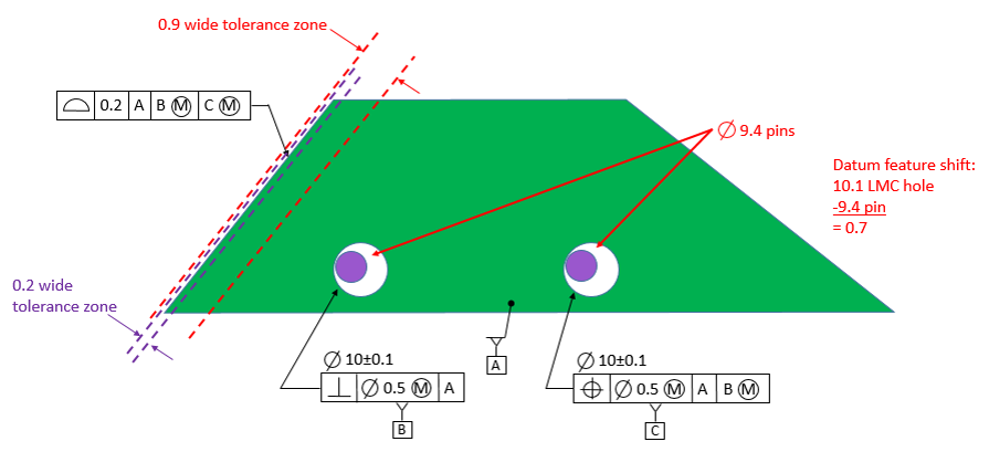
Now we have the same part with the same profile tolerance except the datums are referenced at MMB.
Now the gage has fixed size pins. The diameter of the pins is 9.4. This allows the part to shift on the gage by up to 0.7 if the datum holes are produced perfectly perpendicular to datum [A] and at their LMC size. While the orientation of the surface relative to datum [A] must remain within a 0.2 tolerance zone, the location now lies with a tolerance zone that could be as wide as 0.9 relative to the datum features. This dwarfs the original 0.2 and could have a big effect on the product.
The lesson here is, do not be one of those designers who blindly either puts MMC and MMB on no features of size or on all features of size. Know what the MMC or MMB modifier mean, and use them where they should be used and not where they should not be used.
The lesson here is, do not be one of those designers who blindly either puts MMC and MMB on no features of size or on all features of size. Know what the MMC or MMB modifier mean, and use them where they should be used and not where they should not be used.
As long as we are just looking at one surface, we can show the extremes for how the datum features shift. We must recognize that the 0.9 wide tolerance zone is for the location of the surface relative to the datum features. This 0.9 wide tolerance zone is rigidly located to the datum features.
Meanwhile the 0.2 wide tolerance zone is rigidly located to the gage pins.
We see that one extreme is when the datum features, along with the 0.9 wide tolerance zone, shift to the right. The surface of the part is now as far away as it can be from the datum features. The 0.2 wide tolerance zone is at the left side of the 0.9 wide tolerance zone.
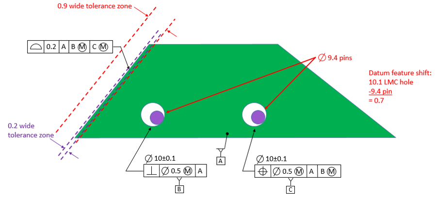
The other extreme is when the datum features, along with the 0.9 wide tolerance zone, shift to the left. The surface of the part is now as close as it can be to the datum features, and the 0.2 wide tolerance zone is at the right side of the 0.9 wide tolerance zone.
Looking at the shift in terms of making the profile tolerance zone bigger is useful for looking at the extremes of what could happen to any given surface. It is the thought process we go through when we perform a limit stack because in a limit stack we are looking for the extremes that are possible. However, the figures below describe what is really physically happening.
The illustration becomes more clear if we consider an all around tolerance. The tolerance zone is always 0.2, and the tolerance zone is always perfectly located relative to the gage pins. The datum feature holes are larger than the gage pins, so the datum feature holes can shift relative to the gage pins and relative to the profile tolerance zone. This shifting will allow the datum feature holes to be closer to some of the surfaces and farther away from other surfaces.
The illustration becomes more clear if we consider an all around tolerance. The tolerance zone is always 0.2, and the tolerance zone is always perfectly located relative to the gage pins. The datum feature holes are larger than the gage pins, so the datum feature holes can shift relative to the gage pins and relative to the profile tolerance zone. This shifting will allow the datum feature holes to be closer to some of the surfaces and farther away from other surfaces.
The figure below shows the datum feature holes shifting toward the left side of the part and away from the right side of the part.
The figure below shows the datum feature holes shifting toward the right side of the part and away from the left side of the part.

The profile requirement is met if the part can fit over the pins, lay flat on datum [A], and all of the outside surfaces fall within the profile tolerance zone. The part can be moved around relative to the pins in order to find a position in which the outside surfaces fit within the tolerance zone.
What does this mean for gaging a complex part? Either do the complex geometric calculations, or measure the part with a CMM and re-create it as measured in a CAD system. You can then create a gage with the appropriate tolerance zone in CAD and determine in CAD whether or not the part meets the requirements as described above.
What does this mean for gaging a complex part? Either do the complex geometric calculations, or measure the part with a CMM and re-create it as measured in a CAD system. You can then create a gage with the appropriate tolerance zone in CAD and determine in CAD whether or not the part meets the requirements as described above.