Straightness
Harley's toy looks pretty straight. But how straight is it? How do we know?
We can define straightness as applied to a surface, and we can define straightness as applied to the center line. We will start out with straightness applied to a surface.
We can define straightness as applied to a surface, and we can define straightness as applied to the center line. We will start out with straightness applied to a surface.
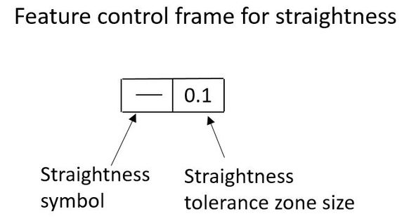
The straightness specification is as shown below.
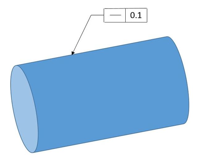
The classic example of applying straightness to a surface is shown below. The straightness callout points directly to the surface of the pin. Therefore we know that the straightness tolerance applies to the surface.
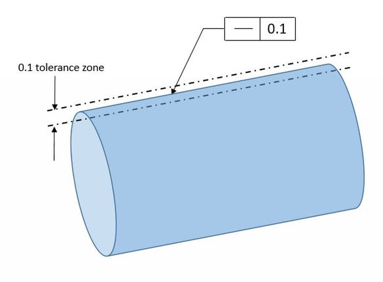
When straightness is applied to a surface, the tolerance zone is always two parallel lines. The figure below shows the tolerance zone for our straightness callout. The edge of the cylinder must fall between two parallel lines 0.1 mm apart.
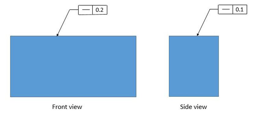
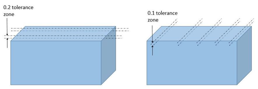
Things get a little more complicated when we talk about straightness on a flat surface. The tolerance zone is still two lines, but it's two lines in each cross section and it's directional. In the figure below we see straightness applied to a block in two different views. We have different straightness values in the different views.
The figure below shows the tolerance zones for the various straightness callouts. The block on the left shows the tolerance zone for the 0.2 straightness control. Note the direction of the lines is parallel to the front view. Only two cross sections are shown. The tolerance applies at an infinite number of cross sections.
Likewise the block on the right shows the tolerance zone for 0.1 straightness control. Note the direction of the lines is parallel to the side view. Five cross sections are shown. Again the tolerance applies at an infinite number of cross sections.
Likewise the block on the right shows the tolerance zone for 0.1 straightness control. Note the direction of the lines is parallel to the side view. Five cross sections are shown. Again the tolerance applies at an infinite number of cross sections.
Just as with flatness, a feature of size without a straightness callout will have its straightness controlled by the size tolerance. Therefore a straightness callout applied to a surface must always be less than the size tolerance so that it refines the straightness control provided by the size tolerance.
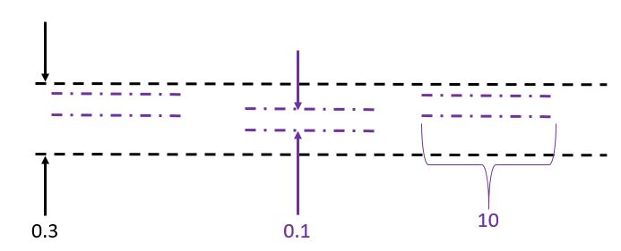
Also just like flatness, straightness can use a refinement. Below we see a refined straightness. It specifies an overall straightness of 0.3 with a refinement of 0.1 per 10 mm (or per 10 inches as the case may be).
Also just like flatness, straightness can use a refinement. Below we see a refined straightness. It specifies an overall straightness of 0.3 with a refinement of 0.1 per 10 mm (or per 10 inches as the case may be).
The figure below shows the tolerance zone. The entire tolerance zone is 0.3 wide, but any given 10 mm or 10 inch length has a tolerance zone 0.1 wide.
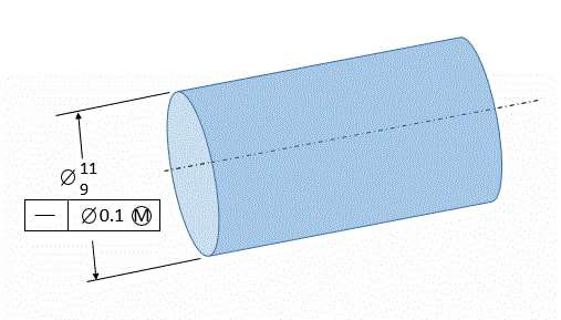
Now let's look at applying straightness to a feature of size. Prior to the 2009 ASME standard, straightness could be applied to any feature of size. In the 2009 standard, the rules were changed such that straightness can be applied to cylindrical features of size but not rectangular features of size. The figure below shows straightness applied, at MMC, to a cylindrical feature of size. We know that the straightness applies to the feature of size because the straightness tolerance is located below the size tolerance.
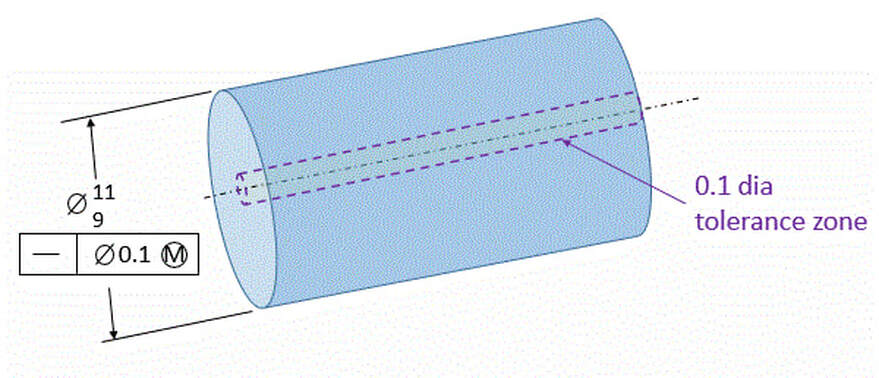
Below we see the cylinder along with the tolerance zone as it is when the pin is at its MMC size. The tolerance zone is a cylinder within which the axis of the pin must fall. Of course, since the axis is not a straight line, we call this imperfect line a Derived Median Line. Since the straightness tolerance is called out MMC, the size of the tolerance zone can vary. When the size of the part is 11, then the size of the tolerance zone is 0.1 diameter. As the size of the pin departs from MMC, we get Bonus Tolerance. That means that as the pin gets smaller, the size of the tolerance cylinder grows by the amount that the part is away from the MMC size.
The animation below shows the different sizes and shapes that the pin can be. Note that the 11.1 virtual condition boundary is never violated.
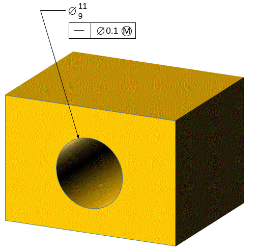
It works the same way for holes. The hole below has a straightness callout below the size dimension. That means that the straightness tolerance applies to the axis of the hole.
The animation below shows the callout with the MMC modifier in the feature control frame. If the MMC modifier were not there, then the tolerance zone for the center line would be a cylinder diameter 0.1 no matter how big or small the hole is. Now the tolerance zone is 0.1 when the hole is produced at its MMC size, but the tolerance zone is allowed to grow as the hole departs from its MMC size. The amount the tolerance zone is allowed to grow is equal to the amount that the hole departs from its MMC size.
Once again the boundary stays constant. So as long as the hole is within its size tolerance, if we can fit an 8.9 dia cylinder through the hole, then we know that it meets its straightness requirement.
When straightness is applied to a feature of size, the straightness value is allowed to be smaller, equal to, or greater than the size tolerance.
When straightness is applied to a feature of size, the straightness value is allowed to be smaller, equal to, or greater than the size tolerance.


