Flatness
Nicholas likes to sleep on a nice, flat surface - preferably carpeted. But how flat is flat?
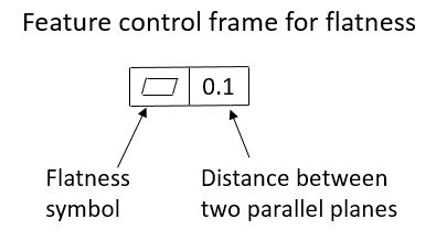
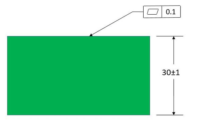
we define flatness by specifying that a surface must fit between two parallel planes that are a specified distance apart. The flatness callout is as shown below.
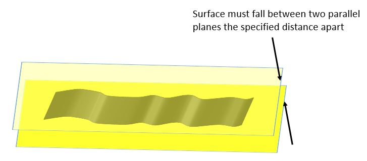
When we look at a surface closely enough, it will never be perfectly flat. But our flatness control tells us that the wavy surface must fall in between two planes the specified distance apart as shown below.
Note that flatness never has a datum callout. None of the form tolerances have datum callouts. Something is either flat or not flat on its own. It is never flat relative to something else.
Note that flatness never has a datum callout. None of the form tolerances have datum callouts. Something is either flat or not flat on its own. It is never flat relative to something else.
Flatness can apply to either an outside surface of a part or a centerplane.
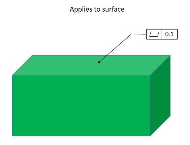
When flatness applies to an outside surface, the feature control frame points at that surface or is on an extension line connected to that surface.
When flatness applies to an outside surface, the feature control frame points at that surface or is on an extension line connected to that surface.
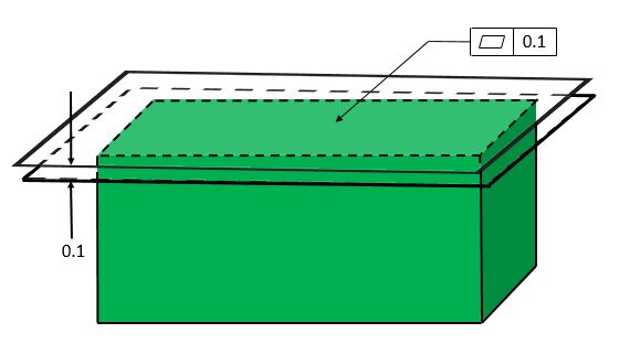
The surface then, must fall between two parallel planes that in this case are 0.1mm apart.
Note that when flatness is applied to a surface, it does not affect the size of the part.
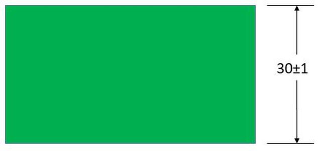
In the part below, the size of the part is controlled by the coordinate tolerance. A flatness control is applied to the top surface. We know that the flatness applies to the surface because the flatness control points to the top surface. The flatness tolerance zone is two parallel planes 0.1 mm apart.
In the part below, the size of the part is controlled by the coordinate tolerance. A flatness control is applied to the top surface. We know that the flatness applies to the surface because the flatness control points to the top surface. The flatness tolerance zone is two parallel planes 0.1 mm apart.
The size can never be greater than 31 or less than 29. Note below that when the part is created at size 31, the form must be perfect per rule #1. Therefore the tolerance zone has its top plane at 31 and its bottom plane at 30.9. Flatness applied to a surface never affects the outer boundary of a part.
When the part is size 29, it can never be less than that. So the bottom plane of the flatness tolerance will be at 29 and the top plane will be at 29.1.
Anywhere it between, the flatness tolerance zone is just any two parallel planes anywhere and in any orientation that will contain the entire surface of the part. If the entire surface of the part cannot be contained between some two parallel planes 0.1 apart, then the flatness control is violated.
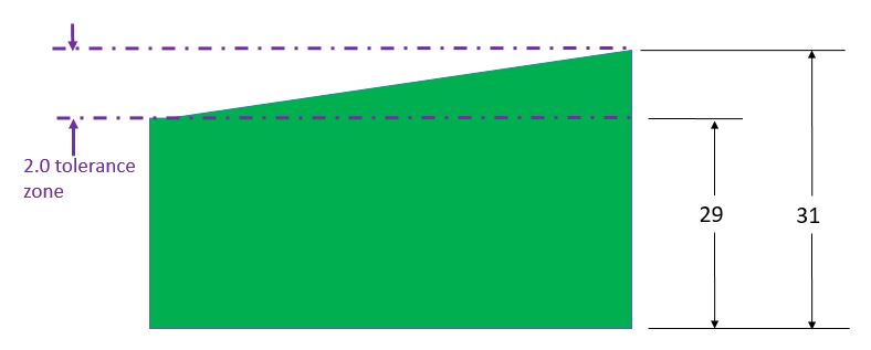
One more thing to note about flatness applied to a surface is that the size tolerance itself provides a flatness tolerance. In the figure below, the part has only a size tolerance. The size tolerance provides a flatness tolerance that is equal to the size tolerance.
The figure below shows us the flatness tolerance that is provided by the size tolerance. The part could be 29 high at one end and 31 high at the other end. This gives us a flatness tolerance that is equal to the size tolerance.
Note that because the size tolerance already provides a flatness tolerance, any flatness tolerance we specify must be smaller than the size tolerance so that the flatness tolerance we specify will refine the size tolerance provided by the size tolerance.
Note that because the size tolerance already provides a flatness tolerance, any flatness tolerance we specify must be smaller than the size tolerance so that the flatness tolerance we specify will refine the size tolerance provided by the size tolerance.
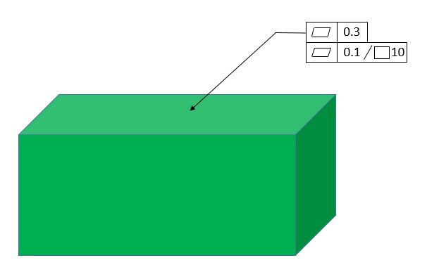
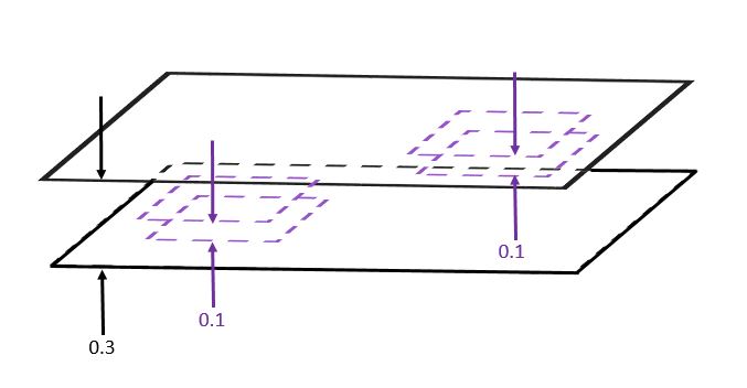
When we apply flatness to a surface, we can also do a refinement. We can apply our flatness control as below. The top line specifies a 0.3 wide tolerance zone that covers the entire surface.
The bottom line specifies smaller tolerance zones within the larger tolerance zone. Each of these smaller tolerance zones is 0.1 wide and does not cover the entire surface. Each 10X10 square has a tolerance zone 0.1 wide.
The bottom line specifies smaller tolerance zones within the larger tolerance zone. Each of these smaller tolerance zones is 0.1 wide and does not cover the entire surface. Each 10X10 square has a tolerance zone 0.1 wide.
The figure below shows the tolerance zone for the flatness control above. The overall tolerance is 0.3, so the entire surface must fit between two parallel planes that are 0.3 apart. But any given 10X10 square on the surface must fall between two parallel planes that are 0.1 apart.
Note that instead of a square symbol in the lower line of the straightness control, we could have used a diameter symbol. In that case each 10 diameter circle on the surface would be required to fall between two parallel planes that are 0.1 apart.
Note that instead of a square symbol in the lower line of the straightness control, we could have used a diameter symbol. In that case each 10 diameter circle on the surface would be required to fall between two parallel planes that are 0.1 apart.
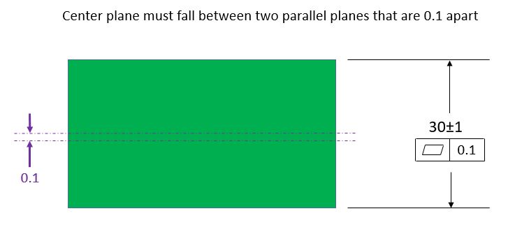
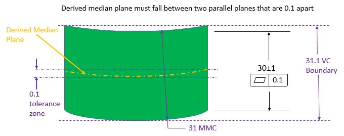
Now let's look at what happens when flatness is applied to a center plane. In the figure below, the flatness control is shown underneath the size tolerance. This tells us that the flatness control applies to the center plane of the part. When flatness applies to the center plane of the part, it allows rule #1 to be overridden. Now instead of the part being required to fit into the MMC boundary of 31, the part can occupy a boundary as large as 31.1.
In the figure below we see that something we call the Derived Median Plane is what must fall within the tolerance zone. Once we acknowledge that the center plane is not really a plane, we must call it something else. The Derived Median Plane gets its name from the fact that it is derived by taking a bunch of two point measurements and having all of the median points of those measurements form a plane that is not really a plane.
All of this is very confusing and difficult to measure. So we tend to focus our attention on the fact that the part can now be at its MMC size and still have the specified form error. Therefore the new boundary that it cannot violate is equal to the MMC size plus the flatness tolerance which in this case adds up to 31.1.
All of this is very confusing and difficult to measure. So we tend to focus our attention on the fact that the part can now be at its MMC size and still have the specified form error. Therefore the new boundary that it cannot violate is equal to the MMC size plus the flatness tolerance which in this case adds up to 31.1.
We can now introduce the concept of Bonus Tolerance. In the figure below, we have the MMC symbol inside the feature control frame. Without that symbol, the flatness tolerance was Regardless of Feature Size (RFS). So until now the tolerance zone was 0.1 no matter if the actual part were produced at its MMC size of 31 or its LMC size of 29 or anywhere in between.
Now with the MMC symbol, the flatness tolerance of 0.1 applies at the MMC size of 31. As the size of the part gets smaller, the size of the tolerance zone grows by an amount equal to how far the actual size is away from the MMC size. So when the actual part is produced at size 30, the size of the tolerance zone is 1.1. And when the actual part is produced at the LMC size of 29, the size of the tolerance zone is 2.1 This additional flatness tolerance that we are allowed as a result of the actual size departing from MMC is called Bonus Tolerance.
The boundary that cannot be violated remains at 31.1, and when we use the MMC modifier, we like to call this boundary a Virtual Condition Boundary. The size of the part and the size of the tolerance zone work together to allow the maximum amount of flatness error without violating the 31.1 Virtual Condition Boundary.
The concept of never violating the virtual condition boundary helps us with gaging the part. As long as the size of the part falls within the size limit everywhere on the part, we can test for the flatness by passing the part between to planar objects that are exactly 31.1 apart. If the part is within its size limits and it passes between the two planes 31.1 apart, then we know it meets its flatness requirement.
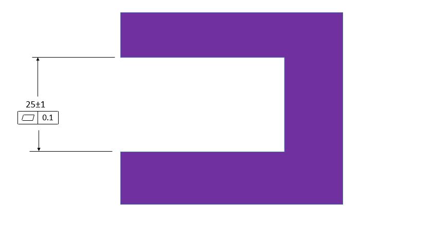
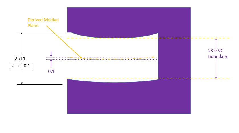
It works the same way for slots. The slot below has a flatness callout below the size dimension. That means that the flatness tolerance applies to the center plane of the slot.
The figure below shows the slot at its MMC size with the max allowable flatness error. The derived median plane must fall between two planes that are 0.1 apart. The slot will never violate a constant Virtual Condition boundary of 25-1-0.1 = 23.9
Since there is no MMC modifier in the feature control frame, the size of the tolerance zone is constant regardless of whether the slot size produced is at MMC or LMC or anywhere in between.
Since there is no MMC modifier in the feature control frame, the size of the tolerance zone is constant regardless of whether the slot size produced is at MMC or LMC or anywhere in between.
The animation below shows the callout with the MMC modifier in the feature control frame. Now the tolerance zone is 0.1 when the slot is produced at its MMC size, but the tolerance zone is allowed to grow as the slot departs from its MMC size. The amount the tolerance zone is allowed to grow is equal to the amount that the slot departs from its MMC size.
Once again the boundary stays constant. So as long as the slot is within its size tolerance, if we can fit a 23.9 width block in the slot, then we know that it meets its flatness requirement. The MMC modifier tells us us that we can gage the part with a fixed size gage.
In all cases, when flatness is applied to a feature of size, the flatness tolerance value may be smaller than, equal to, or larger than the size tolerance value.
In all cases, when flatness is applied to a feature of size, the flatness tolerance value may be smaller than, equal to, or larger than the size tolerance value.


