Angularity
Angularity controls the orientation of a surface or a feature of size at any angle, not just 0 degrees or 90 degrees.
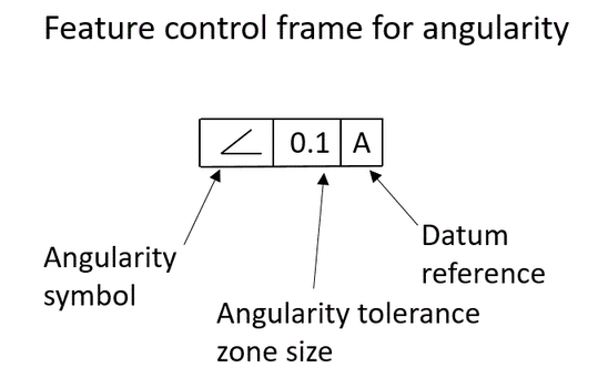
The feature control frame for angularity is shown below:
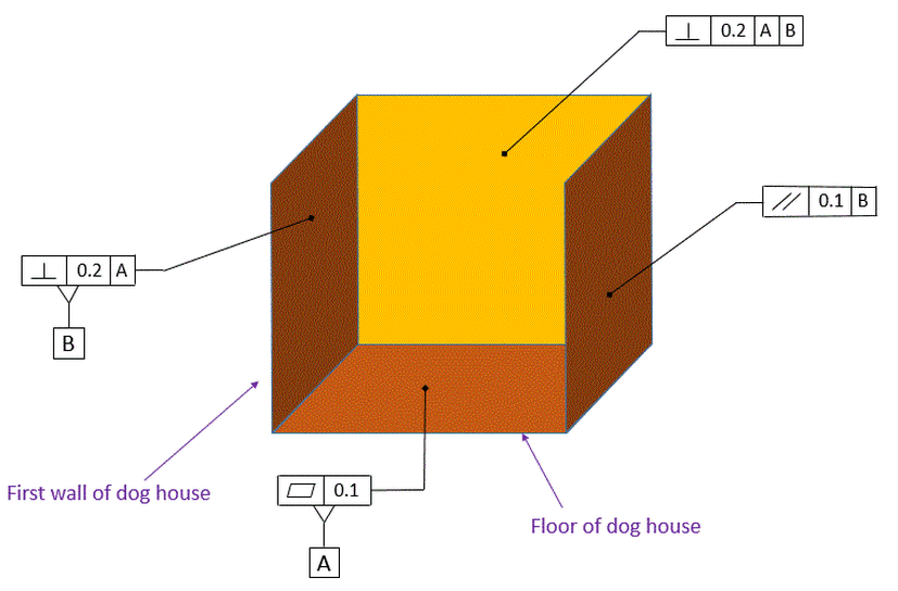
When I teach GD&T, if I am running tight on time, I skip Perpendicularity and Parallelism and go right to Angularity. I tell the students that if they understand Angularity, then they understand Perpendicularity and Parallelism. That's because Perpendicularity and Parallelism are just special cases of Angularity. The Y14.5 committee recognizes this, and that is why according to the 2009 standard it is legal to put Angularity everywhere that you would otherwise put Perpendicularity or Parallelism.
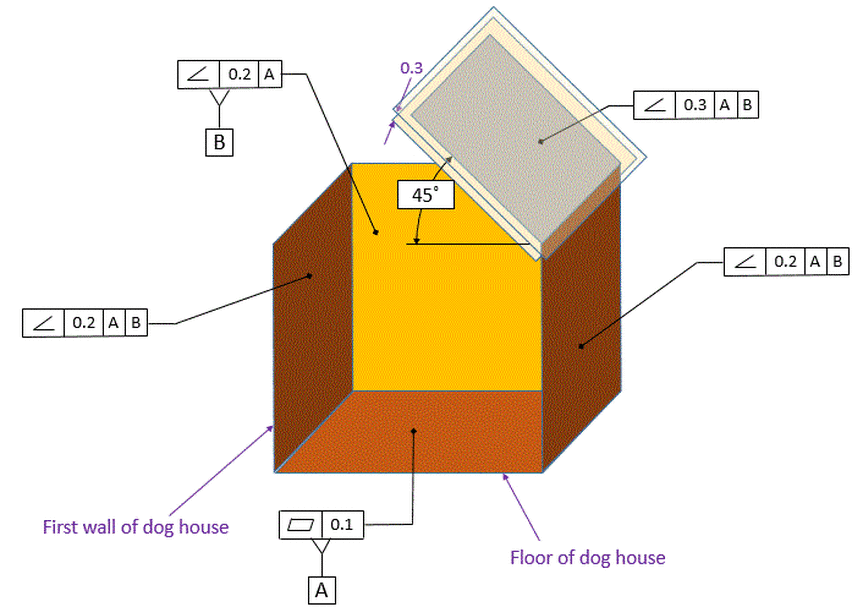
In the figure below, we see two instances of perpendicularity and one instance of parallelism. We could change both of the perpendicularity callouts to angularity and change the parallelism callout to angularity and the meaning would not change.
In the figure below, we see two instances of perpendicularity and one instance of parallelism. We could change both of the perpendicularity callouts to angularity and change the parallelism callout to angularity and the meaning would not change.
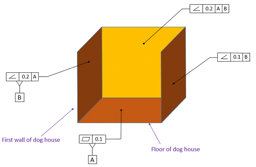
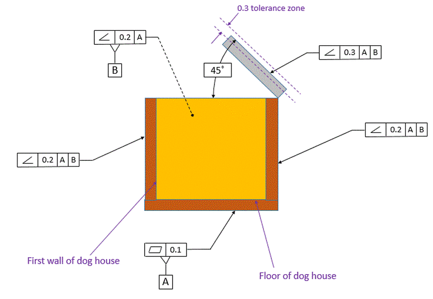
In the figure below, the Perpendicularity callouts and Parallelism callout have been replaced with Angularity callouts. The meaning is exactly the same as the figure above.
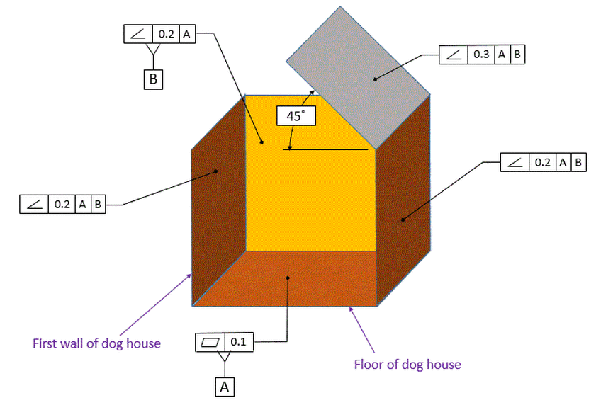
Now if we want to attach one of the roof pieces to our dog house, we will want to control the angle of he roof piece relative to the floor. In a perfect world, we want the roof piece to be on a 45 degree angle relative to the floor. So we use an angularity control. With angularity, we must always have a datum reference and a basic angle. Note that this time we have both datums [A] and [B] called out in order to control the angles to both datum [A] and datum [B].
The angle to datum [A] is explicitly called out with the 45 degree basic angle. The angle to datum [B] is an implied basic 90 degree angle. Zero degree angles and 90 degree angles are never called out, but they are assumed. When using coordinate tolerancing, the zero and 90 degree angles are nominal angles and the tolerances are usually controlled by title block tolerance. When using GD&T, the zero and 90 degree angles are basic. The tolerance is controlled by whichever geometric tolerances apply.
The angle to datum [A] is explicitly called out with the 45 degree basic angle. The angle to datum [B] is an implied basic 90 degree angle. Zero degree angles and 90 degree angles are never called out, but they are assumed. When using coordinate tolerancing, the zero and 90 degree angles are nominal angles and the tolerances are usually controlled by title block tolerance. When using GD&T, the zero and 90 degree angles are basic. The tolerance is controlled by whichever geometric tolerances apply.
Our roof piece is now required to be between two parallel planes that are 0.3 apart. These planes are exactly 45 degrees to datum [A] and exactly 90 degrees to datum [B]. Note that there is no sense of a max or min angle. There are just two parallel planes that are 0.3 apart and the entire surface must fit between those two planes. Therefore the Angularity control is controlling both the angle and the flatness of the surface.
Consider the fact that we will likely make our dog house out of plywood. The plywood will have thickness and appear as below in the front view. As called out, it is the top surface of the roof piece that must fall within the angularity tolerance zone.
Plywood often has imperfections in the surface, little gouges or other small holes where the wood may contain a knot. We don't care about those small imperfections because we are going to cover our plywood roof piece with felt and then nail shingles over it. Therefore while we want our angularity control to limit the roof piece's angle, we do not want it to impose a flatness control.
Plywood often has imperfections in the surface, little gouges or other small holes where the wood may contain a knot. We don't care about those small imperfections because we are going to cover our plywood roof piece with felt and then nail shingles over it. Therefore while we want our angularity control to limit the roof piece's angle, we do not want it to impose a flatness control.
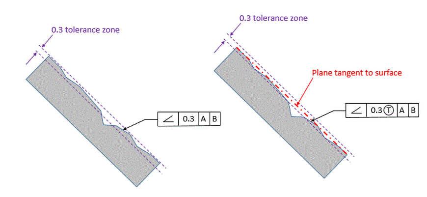
The figure below shows a close up of our roof piece. On the left, we have our angularity callout that limits both the angle and the flatness of the surface. We can see that there are small gouges in the surface that will violate the flatness requirement.
On the right, we have inserted the Tangent Plane Modifier into the feature control frame. The Tangent Plane Modifier is the T in the circle. It indicates that the entire surface is no longer required to fall within the tolerance zone. Now only the plane that is tangent to the surface is required to fall within the tolerance zone. Therefore the angle is still controlled, but flatness is no longer controlled. This is what we want for the roof piece of our dog house.
Note that the Tangent Plane Modifier can be used with Angularity, Parallelism, Perpendicularity, and Profile.
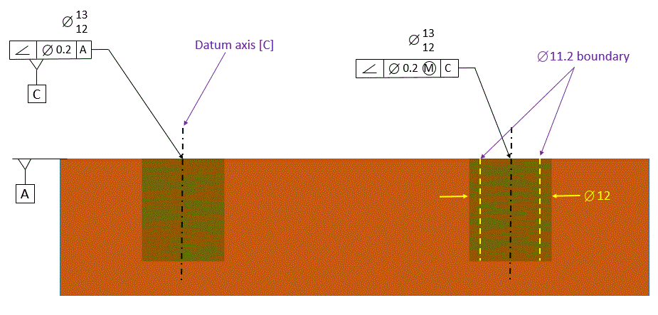
Angularity can also be applied to holes, just as we did with perpendicularity and parallelism. The MMC modifier can also be applied in order to create a Virtual Condition boundary.
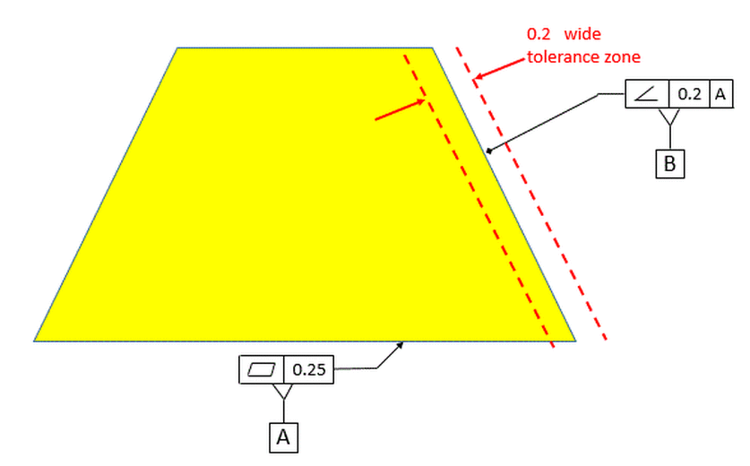
Now we'll look at how datums affect the angularity tolerance zone. The simplest case is shown below. Our measured surface has an angularity tolerance relative to datum [A], and the tolerance zone is stationary as shown.
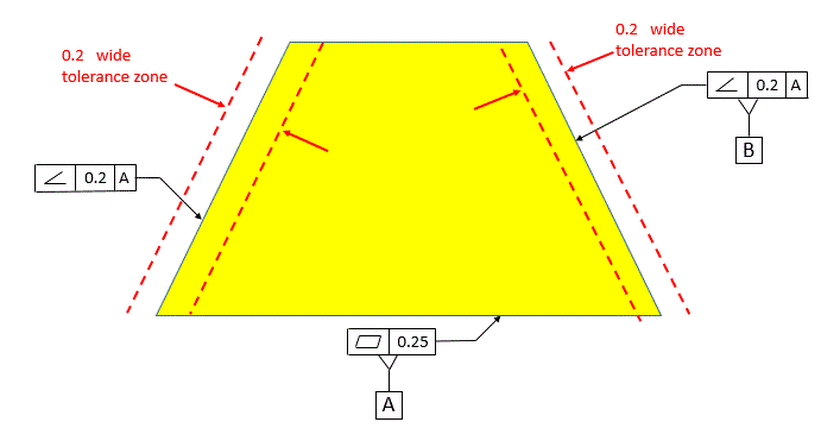
Next we introduce a second surface that also has a stationary tolerance zone relative to datum [A].
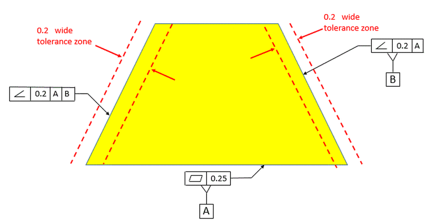
Now we have the surface on the left oriented relative to [A] primary and [B] secondary. Datum [B] in this case is a plane at the exact basic angle that the model specifies for the surface on the right. So datum [B] will not be tangent to the surface on the right. The surface on the right can be on any angle allowed by the 0.2 wide tolerance zone. It might only contact datum plane [B] at two points when held in the gage. The tolerance zone then for the surface on the left maintains a constant angle relative to datums [A] and [B], and its location will follow the surface of the part.
Now we look at the surface on the left oriented to datum [B] and not to datum [A]. The surface on the left is now totally divorced from datum [A]. Datum [B] is now the plane tangent to the surface on the right and is no longer at the specified basic angle relative to datum [A]. So the tolerance zone for the surface on the left shifts as the surface on the right shifts within its tolerance zone relative to datum [A].

