Parallelism
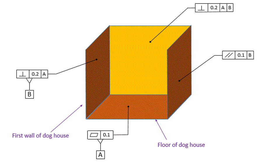
If we are building a dog house and already have a floor and two walls, we may want to add a third wall. We can choose to specify the wall's orientation through a Parallelism callout.
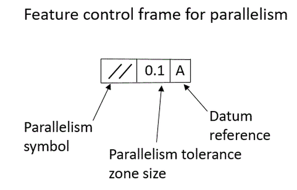
The feature control frame for parallelism is shown below:
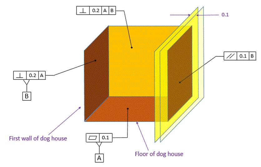
In our case we have specified that wall on the right must be parallel to datum [B] within 0.1.
The tolerance zone for our parallelism control is shown below. The wall on the right must fall between two parallel planes that are exactly 1.0 apart. These two parallel planes are also perfectly parallel to datum [B].
Note that our parallelism callout is controlling the orientation and the flatness of the surface, but it does not control location. As shown so far, the location of the wall is not called out. Parallelism never controls location.
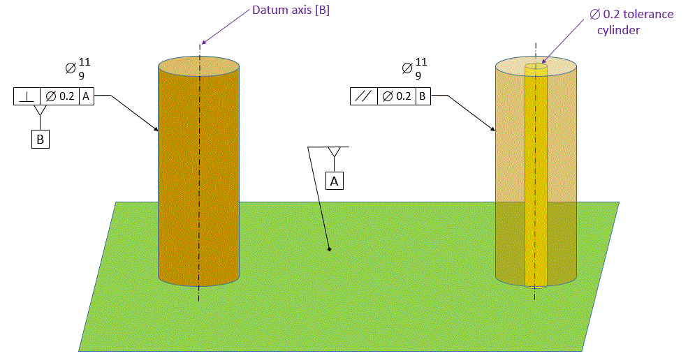
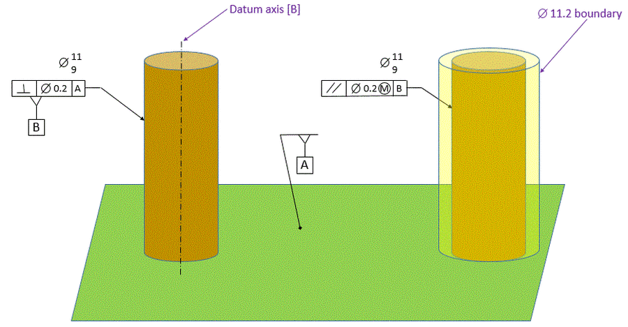
Now we will apply parallelism to a feature of size. In the Perpendicularity section we saw how to specify a perpendicularity requirement for a fence post. Now we will apply parallelism to make our second fence post parallel to our first fence post. We apply our parallelism to the post on the right in the figure below. The parallelism specifies that there is a 0.2 diameter tolerance cylinder. This tolerance cylinder is exactly parallel to datum [B]. Datum [B] is the axis of the unrelated actual mating envelope of the post on the left. Our parallelism requirement says that the axis of the unrelated actual mating envelope of the post on the right must fall within the tolerance cylinder. Remember that our parallelism control says nothing about where the tolerance cylinder is. It only specifies that the tolerance cylinder must be parallel to datum [B].
The figure below shows how the post on the right can tilt back an forth while the axis of its unrelated actual mating envelope stays within the specified tolerance cylinder.
If we intend to fit something over our fence posts, such as a section of fencing, we must make sure that our fence post does not violate the boundary that represents the adjoining part. If we want to protect a boundary, we call out our parallelism MMC. The boundary that the fence post will not violate is the virtual condition boundary of the post. In our case the virtual condition boundary is the largest post plus the parallelism error allowed at MMC. Therefore it is 11+0.2=11.2
We can see below the post inside its virtual condition boundary. When the post is manufactured at dia 11, it can tilt up to 0.2 without violating the 11.2 virtual condition boundary. When the post is manufactured at 9, it can tilt up to 2.2 without violating the 11.2 virtual condition boundary. The extra amount that the post can tilt as a result of being thinner than 11.2 is called bonus tolerance. The bonus tolerance is extra parallelism error allowed as a result of the size of the part.
Note that in reality most posts would be produced at diameters somewhere between 9 and 11. So in order to calculate bonus tolerance allowed for a given post, that post would need to be measured. Then the bonus tolerance allowed would be equal to the difference between the MMC size and the actual size. The total parallelism tolerance allowed would be equal to the 0.2 allowed at MMC plus the bonus tolerance allowed for that particular part.
Note that in reality most posts would be produced at diameters somewhere between 9 and 11. So in order to calculate bonus tolerance allowed for a given post, that post would need to be measured. Then the bonus tolerance allowed would be equal to the difference between the MMC size and the actual size. The total parallelism tolerance allowed would be equal to the 0.2 allowed at MMC plus the bonus tolerance allowed for that particular part.
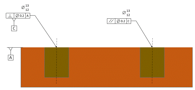
If we dig holes for the fence posts, we want the holes to be parallel to each other. The hole on the left is our datum hole. We want the hole on the right to be parallel to the datum hole within 0.2
Our parallelism control specifies that there is a 0.2 diameter cylindrical tolerance zone that is exactly parallel to datum [C]. The unrelated actual mating envelope of our considered hole must be inside this tolerance cylinder. It says nothing about where the considered hole is. It only specifies the orientation of the hole.
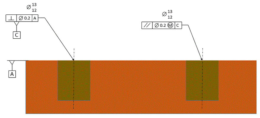
If we want to put a fence post in our considered hole, and if the fence post is going to be parallel to the one that goes in our datum hole, then we can make sure our fence post will always fit into our condsidered hole by using the MMC modifier. This will ensure that a boundary that is parallel to the datum hole will never be violated.
The parallelism with an MMC modifier defines a boundary that is perfectly parallel to datum axis [C]. The size of this boundary is equal to the Virtual Condition size of the hole: 12-0.2=11.8
When the hole is at its MMC size of 12, it can tilt by 0.2 without violating the VC boundary of 11.8. As the hole grows from 12 dia to 13 dia, the larger hole can tilt more without violating the 11.8 dia boundary. This extra parallelism error that is allowed when the hole is larger than 12 is called Bonus Tolerance.
As long is our hole meets the requirements of the parallelism tolerance, the fence post will always be able to slide into the 11.8 dia boundary.

